http://www.chemistrymag.org/cji/2002/049044pe.htm |
June 30, 2002 Vol.4 No.9 P.44 Copyright |
(Department of Chemical Engineering, Wuhan Institute of Chemical Technology, Wuhan 430073; #Educational Administration Department, Zhejiang University of Technology, Hangzhou 310014, China)
Received April
9, 2002. Supported by the National Natural Science Foundation of ChinaAbstract Based on a number of
investigations, a submerged circulative impinging stream reactor (SCISR) is developed for
liquid and/or liquid-solid systems. The major features of SCISR are its special flow
configuration of plug flow-perfect mixing in series and significantly promoted micro
mixing in the impingement zone, both of which have been shown experimentally. In
several practical cases, e.g., preparation of "ultra fine" white carbon black, SCISR exhibits much better performances than
the traditional stirred tank reactor (STR). In addition, SCISR has a number of advantages
in mechanical structure prior to STR, and thus is of potential in application.
Keywords Impinging streams, Reactor, Mixing, Flow configuration, Residence time
distribution
1 INTRODUCTION
Mixing status influences greatly on the performance of reactor for liquid and/or
solid-liquid reactions. Traditionally, stirred tank reactors (STR), operated continuously
(CSTR) or in batch (BSTR), are used for such kinds of reactions. However, mixing nature of
STR is not good enough. In some cases this may result in poor efficiency.
The concept of impinging streams (IS) was presented first by Elperin [1].
It has been proved to be one of the most effective methods enhancing transfer between
phases and promoting mixing, especially micro mixing [2,3]. Based on a number
of studies, the author of the present paper developed a submerged circulative impinging
stream reactor (SCISR)[4], which exhibits well performances in a number of
application instances and is of great potential in application.

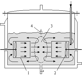
Fig.1 A brief view of the SCISR
1£drawing tube 2£propeller 3£impingement zone 4£outlet
2 BASIC DESIGN OF SCISR
A brief view of SCISR is shown in Fig. 1. Basically,
it consists of streams impinging against one another and circulation flow. The latter
enables one to set mean residence time arbitrarily to meet requirement of most reaction
systems. The internal elements of the reactor are so arranged that two opposite streams of
essentially the same mass flow rate from the co-axial drawing tubes impinge horizontally.
The circulation of flow makes the impingement being under submerged conditions. The
propellers mounted inside the two drawing tubes accelerate the streams from near zero to a
considerably high velocity, resulting in strong turbulence, enhanced transfer condition, and greatly promoted
mixing in the impingement zone.
3 MIXING TIME IN SCISR

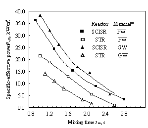
* PW£pure water; GW£solution of glycerin in water
Chen [5] measured mixing time in both SCISR and STR with effective volumes of 3.6¡Á10-3 and 0.6
¡Á10-3 m3, respectively, by an input-response technique of electroconductivity, with KCl solution as the tracer. The criterion for determining mixing time is that both the relative variations in tracer concentration (electroconductivity) with time at every measuring point and concentration difference between every two points are ¡Ü5%, as commonly used. Both reproducibility and regularity of the data obtained are well. A part of the results are shown in Fig. 2. As can be seen, the mixing time in SCISR is always longer than that in STR by about 20-80% under the conditions of the same specific effective power inputted, Peff. This is totally opposite to the earlier conclusion by Brauer[6], who showed the data of dimensionless mixing time in a stagnation jet mixer, which is of a flow configuration similar to that in SCISR, much shorter than in STR.4 FLOW CONFIGURATION AND RTD IN SCISR
4.1 Flow configuration and RTD model

Fig. 3 Simplified model for the flow in SCISR
with
where
![]() (3)
(3)
E0 is determined by
![]() (4)
(4)
Both the sub-RTPs of Em and Ep are well known as
![]() (5)
(5)
Where qm and qp denote the main residence times in
perfect mixing and plug flow regions, respectively. Substituting Eq. (5) into Eq. (4)
yields
![]() (6)
(6)
Note that the material, with the tracer, is inputted at the
inlet of the drawing tube, of which the volume occupies about one tenth of the plug flow
region. So, there must be E0=0 for t<qp/10. If the
volume fraction occupied by the perfect mixing region is fm, we have
![]()
Eq. (6) thus becomes
 (7)
(7)
Define convenient constants A and B as
![]() (8)
(8)
Eq. (7) then is simplified into
![]() (9)
(9)
and its Laplace transform is
![]() (10)
(10)
Using Eq. (10) and the convolution integral theorem, the
Laplace transforms of every sub-RTP in Eq. (1) are obtained to be
![]() (11)
(11)
Substituting Eq. (11) into Eq. (1) and rearranging yield
![]() (12)
(12)
Inversion of Eq. (12) leads to
![]() (13)
(13)
The right side of Eq. (13) is just the
series expansion expression of an exponential function. Thus, we come to the overall RTP
for the SCISR under consideration:
![]() (14)
(14)
In the RTP model above, at least one of
the parameters fm and R must be determined for simulation. The perfect mixing
region is without physical boundary, and a proper evaluation is called. Fortunately, the
surging appearance of the impingement zone is quite different from other regions in the
operation of SCISR, and thus repeated visual observations may yield relatively
correct data. For the experimental reactor and under the operating conditions employed, a
value of fm=0.186 is obtained. Due to the difficulty in measuring the stream
velocity inside very short tubes with small diameter, the values for R are determined by
fitting measured data with the model.

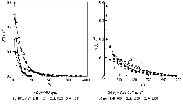
Fig. 4 Comparison between the results measured and calculated with Eq.
(14) for RPT in SCISR
4.2 Experimental results for RTD
To confirm reasonability of the proposed flow configuration, Chen [5] measured
also RTD in SCISR at various propeller rotary speeds and feed rates by the same technique
and with the same tracer as used for mixing time measurement. A part of the results are
shown in Fig. 4 as the data points, and the results computed with the model above under
various conditions are also given in the same figure as the curves for comparison. As can
be seen, the model characterizes RTD behavior of SCISR well, suggesting the flow
configuration proposed being feasible, i.e., the SCISR does include regions without
mixing, which occupies a large volume fraction, and thus the macro-mixing time in SCISR
should be longer than in STR.
It is predicted that the regions without mixing in SCISR are useful for
certain processes, e.g., reaction- precipitation or crystallization. In these cases, low
super saturation and poor mixing in these region may favor surface inactivation of fine
particles or growth of crystals to yield ultra fine particles or large crystals with
narrow size distribution.
5 MICRO MIXING IN SCISR
Global mixing time in SCISR is longer than in STR, on one hand, while the former exhibits
much better performance than STR in a number of practical cases, on the other. The only
reasonable explanation is that IS promotes micro mixing more effectively.
Xiao [9]
studied experimentally micro mixing in SCISR with the series-parallel reactions scheme
below
A + B ![]() R
rate constant: k1
R
rate constant: k1
R + B ![]() S
rate constant: k2 << k1
S
rate constant: k2 << k1
as employed commonly in the recent years£¬where B is
the limiting reactant. Since the second reaction producing Product S is much slower than
the first, the characteristic reaction time constant tR for the scheme can be
assumed to equal the pseudo, first-order time constant of the second reaction, 1/(k2CB0),
where CB0 is the initial concentration of B after mixing. The experimental
method and all the conditions, including reagents and their concentrations, are
essentially the same as used by Mahajan et al. [3], which yield a value of 193
ms for tR. The micromixing time scale in SCISR Xiao characterized in a wide
range of rotary speed of the propellers is less than 193 ms, suggesting well micromixing,
and the detailed results will be reported elsewhere. Note that, the impingement zone
(perfect mixing region) occupies only a small volume fraction (less than 20%), as
described above. So, the results Xiao obtained suggest that IS does promote micromixing
very efficiently.
However, the mechanism of IS promoting micromixing is not clear enough
by now, and remains to be investigated.
6 PERFORMANCE AND FEATURES OF SCISR
Some reaction systems are tested with SCISR. In all the cases it shows well performance [8].
6.1 Preparation of "ultra fine" white carbon black
Chen [5] studied comparatively the preparation of white carbon black in both a
SCISR and a STR, with effective volumes as reported in Section 3, simply by the reaction
H2SO4 + Na2SiO3 + aq = Na2SO4
+ SiO2¡Á nH2O + aq
The experiments result in the following: (1) The product particles obtained in the SCISR
operated in batch are sized from 0.5 to 2.0 with the averages of 1.1-1.6 mm, and both reproducibility and
regularity of the data are very good, (2) Continuous operation in the same reactor yields
the same results, and (3) The product particles from the SCISR are finer with narrower
size distribution than that from the STR, both operated in batch, as typically shown in
Fig. 5. It is clear from the figure that SCISR is prior to STR significantly.

Fig. 5 A comparison between particle size distributions of white carbon
black prepared in SCISR and STR
(a) 0.6¡Á10-3 m3 STR l (b) 3.6¡Á10-3 SCISR
6.2 Other results of SCISR
application
Expect to the process described above, the following results are interesting:
(1) The crystallization of an organic compound in a STR needs ~24 h, while, with SCISR,
the crystallizing time can be shortened to about 10 h.
(2) The reaction of stearic acid with lime producing calcium stearate. In comparison with
STR, SCISR enables one to use higher reactant concentrations and shorter reaction time,
resulting in much higher production per unit volume (over 4 times).
6.3 Other features of SCISR
With proper design, SCISR behaves all the functions
as STR can, such as operation under pressure or vacuum, continuously or in batch, with
heating or cooling, etc. In addition, SCISR has a
number of advantages in mechanical structure prior to STR, e.g., very short rotary axes, low requirement for speed change,
easier sealing, without the problem of corrosion at the gas-liquid interface, and the
possibility of arranging larger surface area for heat exchanging because of its
non-circular cross-section and large annular chamber.
7 CONCLUSION REMARKS
The most important features of the submerged circulative impinging stream reactor are the
special flow configuration of circulative perfect mixing-plug flow in series and
effectively promoted micro mixing in the impingement zone. Also, it has a number of
advantages in mechanical structure prior to traditional stirred tank reactor. In several
practical cases SCISR exhibits much better performance than STR. It is of potential in
application to many reaction processes, especially to preparation of ultra fine materials
by wet processes. Hopefully it will become a multifunctional equipment.
NOTATION
A,B,R,S component variables
A, B convenient constants defined
by Eq. (8)
C concentration, mol¡Á m-3
E residence time distribution probability function, s-1
fm volume fraction perfect mixing region,-
k1,k2 reaction rate constants, m3¡Á mol-1¡Ás-1
N rotary speed, rpm
Peff specific effective power inputted, W¡Ám-3
R circulation ratio, -
S selectivity of reaction
t time variable, s
tR characteristic reaction time constant, s
V0 volume flow rate, m3¡Ás-1
VR effective volume of reactor, m3
Greek letters
qm
mean residence time in perfect mixing region, s
qp
mean residence time in plug flow region, s
ACKNOWLEDGEMENTS
The authors gratefully thank the financial supports from the National Natural Science Foundation of China (No29276260 and 20176043) and the Open Research Foundation of the Multiphase Reaction Laboratory of Process Engineering Institute for the projects involved in this paper.
EFERRENCES
[1] Elperin I T. Inzhenerno-Fizicheskii Zuhrnal (Engineering Physics J,
Russ), 1961, (6): 62-68.
[2] Tamir A. Impinging Stream
Reactors£Fundamentals and
applications. Amsterdam: Elsvier, 1994.
[3] Mahajan A J, Kirwan D J. AIChE J, 1996, 42 (7): 1801-14.
[4] Wu Yuan. CN Patent ZL00230326.4, 2000.
[5] Chen Yu. ME Thesis, Zhejiang University of Technology, 1998.
[6] Brauer H. Ger Chem Eng, 1981, (4): 144.
[7] Sinclair C G, McNaughton K J. Chem Eng Sci, 1965, 20: 261.
[8] Wu Yuan. Chem Eng Progress (Huagong Jinzhan), 2001, 20 (11): 8-13.
[9] Xiao Yang. ME Thesis, Wuhan Institute of Chemical Technology, 2002.