http://www.chemistrymag.org/cji/2001/035020pe.htm |
May 1,
2001 Vol.3 No.5 P.20 Copyright |
Pang Wenmin, Wang Jianli, Fan
Chenggao, Zhu Qingren
(Structure Research Laboratory, USTC, Hefei, Anhui 230026, China )
Received Nov. 9, 2000; Supported by the National Natural Science Foundation of China (No.29874031)
Abstract For a better understandng of the mechanism of Ec (threshold field) in ER fluids, a new testing method, Saturated Electric Field (SEF) was designed. The exist of Ec1 and Ec2 is clearly proved and explained. Furthermore, the fitness of two well-known model for ER in different ER systems is defined. The computer simulation also gave out two order parameter j1 = 1.5 and j2 = 4.5, which correspond well to Ec1 and Ec2, respectively.Keywords Electrorheological Fluid (ERF), Polyelectrolytes, Threshold Field
For the potential value in both theory and
applications, Electrorhological (ER) fluids, especially polymer based systems, have
recently attracted increasing attention[1,2]. Although the mechanism of ER was
explained pretty well, further detail studies are still needed to reach a better
understanding.
For example, the exist of threshold fields (E
In the present paper, we afford a new testing mothod named Saturated Electric Field (SEF) in addition to the classic method mentioned above. The only different between the two methods is, the first thing before each test of E vs t s is to add an extremely high elctric field (5kV/mm here) to the ER fluid to make sure the system is "saturated" by the electric field, quit the field after 1 minute, and then add the proposed electric field to test the t s, just the same in classic method. From the advantage of the new method (SEF) as well as computer simulation, we can give the answer for above questions. 1. EXPERIMENTAL
Preparation of ER fluids. The polyelectrolyte selected as dispered phase is polystyrene-CH2COONa(trade name: G751) which was bought from Shanghai Chemical Company. The particle size is 50-70µm. This was dried uder vacuum at 110°C for 24 hours and then immediately dispersed into silicone oil in weight percent of 12.5%.
Apparatuses. As reported in our early paper[6], an effective parall-plate static yield stress testing apparatus, which made by ourselves, is used.
 Fig 1 Optical micrograph under E=0.6kV/mm (100×) |
 Fig 2 Optical micrograph under E=1.0kV/mm (100×) |
 Fig 3 Optical micrograph under E=2.5kV/mm (100×) |
|
 Fig 5 Optical micrograph under after 3 days |
2. RESULTS AND DISCUSSIONS
2.1 Structure relexation of the ER fluid
Fig. 1-4 are the pictures of the ER fluid under a series of increased eclectric field (0-5
kV/mm) at room temperature by optical microscope, showing the development of the
electric-field-induced structure in the ER system. Two critical points, Ec1
(0.6 kV/mm) and Ec2 (2.5 kV/mm), were found during the
process. When E>Ec1, the ER system began to form column structure in some degree(Fig.
3). These single columns changed slightly with the increased field but reformed and
adjusted rapidly and formed a high order structure when E reached Ec2, as shown in Fig.
4. After that, the structure didn't change up to E = 5 kV/mm.
Once formed, the high order structure was very stable even without
electric field at all for a long time(>3days, Fig. 5). So, this kind of ER system is
considered having strong relaxation in its geometry structure. And this unique character
affords the basement for the new testing method SEF.
2.2 Quantitative study of Ec
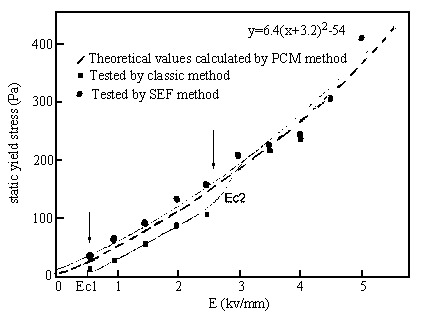
We tested the relationship of E vs t s using the classic method. The results were shown by
the "§"
curves in Fig. 6. The range of electric field is 0-5 kV/mm. Two threshold fields were
observed, Ec1 (0.6 kV/mm) and Ec2 (2.5 kV/mm).
Under the same condition, we switched to the new method SEF also showed
the results in Fig. 6 ("." curve). The saturated
field is 5 kV/mm. Obvisouly, the curve is pretty smooth and no any critic point, and this
curve is basically similar to the theoretical one.
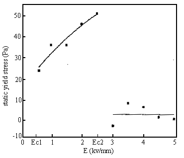
To make it more clearer, the difference
between the two methods were shown in Fig. 7 [ Dts=ts(SEF)
-ts(classic)].
From Fig. 7, when Ec1<E<Ec2, the range Dts of is between 24 - 51 Pa and its average is about 36 Pa
(Considering the corresponding range of E (~ 2 kV/mm), the change of Dts is very small). We noticed that this
average value is almost equal to the value of ts(classic) under Ec1(35 Pa). When E>Ec2, Dts=
0, which means no difference between the two methods at that time.
Why Ec1 and Ec2 appeared
in "classic method" while not in "SEF" for the same ER system? In
"SEF", when the saturated field (5 kV/mm) added, as proved above, the system
formed a high order structure and especially, very stable(strong relaxation). Then when
the field was changed to the proposed value, the system could keep the same high order and
stable structure. In another word, the system had finished a phase transition (or
proximately) before the testing. So, the electric energy received by the system could be
completely used to induce the "fixed" dipoles in stead of "waste" a
part of it to overcome the Brown random moving of particles as in the classic method.
Under this condition, we can conclude that the ER effect and electric field have a simple
one to one relationship in SEF. Thus the factor of K in R. Tao's equation can be omitted
and a single continuous function was got, in which no position for Ec1 and Ec2 like in
"PCM" model.
Now the reason that Ec appeared in "classic method" becomes
clear: when E<Ec1, the electric energy is relatively small compared to the thermal
energy and can not induced any order structure and no any ER effect observed as a result.
When Ec1<E<Ec2, the electric energy increased but only in the same level with the
thermal energy, the degree of the induced structure is pretty low and far from perfect.
There are lots of "voids" in the catenarian (or column) structure. So the
electric energy added could be only partly changed into the "useful"
dipolarization energy, and efficiency of the induced ER effect is lower than that of
"SEF", in which the efficiency is near 100%. The lost part of the efficiency is
believed to be dispersed in the void areas, in which Brown thermal random moving
dominates, so the difference ER effect for the two methods, can properly reflect how much
the thermal energy affects the ER effect. On the other hand, if we reexam the curve of E
vs t s in the range of Ec1 - Ec2 in classic method from this point, the ER effect totally comes
from order parts and those voids contribute nothing, we can guess this part of line in
Fig. 6 is also obey the same rule as the other part(E>Ec2) or the
whole line for SEF and only different in a factor, for example, t s µ AE2 ,
but this prediction needs a further detail study to be proved. When E>Ec2,
electric energy is the dominant one and the high order structure formed, and the
difference of the two methods disappeared naturally.
 |
Fig 6 ts-E relationship curves by two methode |
 |
Fig 7 The relationship curve of Dts-E |
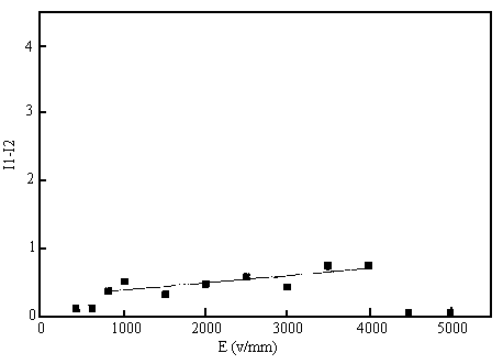
Predictably, the relationship of circuit density I and electric field E has the similar trend under the two testing methods. The results showed it was and consistent with the above analysis. (Fig. 8)

Fig 8 The relationship
curve of
The order geometry
structure (chain structure) is the bridge for electric energy to induce ER effect. And the
structure more perfect, the higher efficiency of the energy is. Additionally, the
structure itself doesn't increase the viscosity of the system, which is shown by the
results under zero field in two testing methods.
The dash line in Fig. 6 is theoretical calculation from PCM model.
Under relatively low field (E<Ec2),
the results from SEF fitted PCM better than those from classic method. But this does not
mean that the PTM model is wrong. The consideration of thermal factor K by R. Tao et al is
reasonable and necessary. Indeed, it is the competetion between k and other factor,
electric U, that causes the exist of Ec1 and Ec2. The two models are both backed by some
experimental results. Which one is really right? Or what's their application and
limitation? Here we try to give some explanations.
(1) They are both reasonable under specific conditions.
(2) To match an experimental result to one theroy is determined by the comprehensive
effect of several factors, such as testing method, range of electric field and the
relaxation of ER system, etc.
(3) When the system has strong relaxation, as shown in the present paper, the effect of
testing method and range of electric field is listed in Table 1.
Table 1. Effect of some factors in strong realaxion ER system
Range of Electric field |
Classic method |
SEF method |
E < E c1 |
2 |
1 |
E c1 < E < Ec2 |
2 |
1 |
E > E c2 |
1 |
1 |
* 1 "Particle Chain Mode"; 2 "Phase Transition Model"
From the table, when the
experimental results are got by classic method, they are not fitted or explained by only
one model, and the range of electric field need to be considered to chose a model. When
the results are from SEF method, it is possible and necessary to use PCM model. Of course,
this does not mean that PCM is better than PTM, because the system here has strong
relaxation. And the advantage of SEF method can be only shown in this kind of condition
(many polymer-based ER system but not all).
(4) When the system has small or no relaxatin, like inorganic ER system or some
polymer-based ER system, testing method and range of electric field has the following
effect (Table 2).
Table 2. Effect of some factors in weak realaxion ER system
Range of Electric field |
Classic method |
SEF method |
E < E c1 |
2 |
2 |
E c1 < E < Ec2 |
2 |
2 |
E > E c2 |
2 |
2 |
* 1 "Particle Chain Model"; 2 "Phase Transition Model"
The result has no any surprise. When the realxtion of the system is very small, it is impossible to make the system form a high order structure before test in SEF method, so no difference indeed between SEF and classic method. In a word, PTM model is good for these systems( weak relaxation, some inorganic system).
2.3 Computer Simulation
We used Monta Carlo method to simulate the ER fluid based on R. Tao's phase transition
model. Here we only give out some results about E
When j, the order parameter which indicate the relative value between electric energy and thermal energy, increased from 1 to 5 step by step. We found,
When j <1.5, no any struture in the system.
When j =1.5 or higher but smaller than 4.5, single chain structure appeared.
When j=4.5 or higher, multi-chain struture appeared.
j =1.5 and j =4.5 are two phase transition points and correspond to Ec1 and Ec2, respectively.
3. CONCLUSION
Based on the strong relaxation character of our polyelectrolyte ER system, we study the
mechanism of Ec from a new point by designing the "Saturated Electric Field"
method. The exist of E
REFERENCES
[1] Block H, Kelly J P. J. Phys Rev. D, 1988, 21:
1661.
[2] Treasurer U, Radzilowski, Filisko F E. J. Rheol.,
1991, 35 (6): 1051.
[3] Tao R. Phys. Rev., 1993, E47: 423.
[4] Tao R. Int. J. Mod. Phys., 1992, B6: 2635.
[5] Flisiko F E. J. Rheol., 1990, 34: 539.
[6] Zhu Q R, Su J, Hong K L et al. Functional Polymer,
1997, 10: 1.
