http://www.chemistrymag.org//cji/2001/036026pe.htm |
Jun. 1,
2001 Vol.3 No.6 P.26 Copyright |
Mu Shaolin, Chen Chuanxiang, Shi Yujun#
(Department of Chemistry, School of Sciences,
Yangzhou University, Jiangsu, 225002; #Department of Chemistry, Nantong
Teacher's College, Jiangsu, 226007, China)
Abstract Polyaniline was
synthesized chemically with ferric sulfate as oxidant. The in situ visible spectra of the
polymerization of aniline in different concentrations of sulfuric acid show that a peak at
720 nm first formed and its absorbance increases with reaction time, and then another peak
at 520 nm gradually formed. Polyaniline with the peak at 720 nm has a small solubility in
water, depending on the concentration of sulfuric acid used for the polymerization of
aniline. However, polyaniline with the peak at 520 nm can completely dissolve in water.
Water-soluble polyanilines with intense color will cause environmental pollution. The IR
spectra and cyclic voltammograms of polyaniline are affected by the concentrations of
sulfuric acid used for the electrochemical polymerization of aniline. The optimum
conditions for "green" synthesis of polyaniline are that the solution consisted
of 0.2 mol dm-3 aniline, 0.1 mol dm-3 ferric sulfate and 0. 2 mol dm-3
sulfuric acid and the reaction temperature was controlled below 15oC.
Keywords Chemical "green" synthesis; Polyaniline; Filtrate
color; In situ visible spectra; IR spectra; Cyclic voltammograms; Conductivity
Among conducting polymers, polyaniline has
been a significant interest due to its high conductivity, good redox reversibility, swift
change in film color with potential and high stability in air. Polyaniline can be used for
batteries[1,2], electrochromic devices [3,4] photoelectrochemical
conversion of light to electricity[5,6], light-emitting diode[7] and
immobilization of enzymes[8,9]. Polyaniline can be synthesized by the
electrochemical polymerization or chemical polymerization of aniline. In the latter,
various oxidants, such as ammonium peroxydisulfate[10-12], sodium
peroxydisulfate[13], potassium bichromate[14] and hydrogen peroxide[15],
were used for the oxidation of aniline monomer. Recently, horseradish peroxidase was used
for the enzyme-catalyzed polymerization of aniline in the presence of hydrogen peroxide,
in which the polymerization was carried out in a 4.3 pH buffered aqueous solution[16].
Among the mentioned above oxidants, ammonium peroxydisulfate has been widely used for the
chemical polymerization of aniline, since polyaniline synthesized in this way has a high
conductivity. However, the filtrate after the electrochemical polymerization of aniline in
aqueous acidic solutions or chemical polymerization of aniline using ammonium
peroxydisulfate as oxidant is dark blue-violet solution, which is very difficult to treat.
Thus the colorful filtrate will cause environmental pollution. The color material produced
during the polymerization of aniline is some water-soluble polyanilines with lower
molecular weight. The main cause for the formation of water-soluble polyanilines is due to
the higher acid concentration or the strong oxidant used for the polymerization of
aniline, for example, ammonium peroxydisulfate has a high reduction potential of 2.01
V(vs.NHE). Based on the results from the electrochemical polymerization of aniline[17-19],
aniline was oxidized at about 0.7 V (vs.SCE). This gives us a clue that the chemical
polymerization of aniline may be carried out using a weaker oxidant. In fact, ferric
chloride was first used as oxidant to prepare chemically polyaniline. The result showed
that the conductivity of polyaniline prepared chemically using ferric chloride is lower
than that prepared using ferric sulfate. Thus we try to employ ferric sulfate as oxidant
to prepare chemically polyaniline, since the reduction potential of the couple Fe3+/
Fe2+ is 0.771 V(vs.NHE).
In this paper, we will report conditions and evidence of
"green" synthesis of polyaniline, the visible spectra during the chemical
polymerization of aniline, conductivity and electrochemical property of polyaniline , and
discuss the change in the IR spectra of polyaniline samples with the polymerization
conditions.
1 EXPERIMENTAL
The chemicals used were all reagent grade. Aniline was distilled before use. A platinum
gauze and an ITO conducting glass were immersed into the ferric sulfate solution without
or with sulfuric acid of a given concentration. Aniline was slowly added into the
solution. The solution was stirred by a magnetic bar during the polymerization process.
The temperature was controlled at 15oC. Aniline was polymerized on the platinum
gauze and ITO conducting glass during the polymerization process. The platinum gauze and
ITO conducting glass with polyaniline will provide tests of the cyclic voltammetry and
visible spectra, respectively. A Model HPD-1A potentiostat-galvanostat was used for the
cyclic voltammetry. The cyclic voltammograms were recorded on a YEW 3036 X-Y recorder. The
scan rate was 80 mV s-1. The visible spectra for the polymerization process of
aniline and polyaniline polymerized on the ITO conducting glass were measured on MPS-2000
spectrometer. In the former, the change in the visible spectra with time was immediately
measured after the addition of aniline into the ferric sulfate solution The mixture was
briefly stirred before the measurement of the spectra. The MPS-2000 spectrometer is a
double-beam instrument. The solution of sulfuric acid and an ITO conducting glass were
used for the references of measurements of visible spectra for the polymerization of
aniline . The conductivity of a pressed polyaniline pellet was measured using a four-probe
technique. IR spectra of polyaniline in KBr tablet were measured on a Nicolet 740 FTIR
instrument.
2 RESULTS AND DISCUSSION
2.1 In situ visible spectra of the polymerization of aniline
The measurements of the in situ visible spectra for the polymerization of aniline were
carried out at an interval of 2.5 minutes between two measurements. Figure 1 shows the in
situ visible spectra of the polymerization of aniline in the solution containing 0.2 mol
dm-3 aniline, 0.1 mol dm-3 ferric sulfate and 0.6 mol dm-3
sulfuric acid. Curves 1 and 8 in Fig.1 represent the first and eighth measurements,
respectively. It is clear that a peak at 720 nm forms as the reaction proceeds and its
absorbance also increases with reaction time. This indicates that aniline was polymerized.
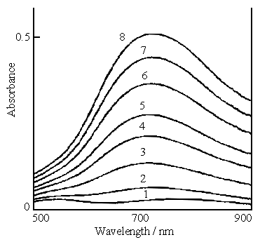 |
Fig.1 In situ visible spectra of the polymerization of aniline, the solution consisting of 0.2 mol dm-3 aniline, 0.1 mol dm-3 ferric sulfate and 0.6 mol dm-3 sulfuric acid. Curves: (1) first measurement, (2) second measurement, (8) eighth measurement. |
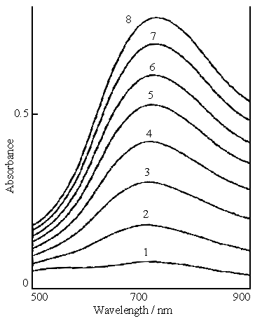 |
Fig.2 In situ visible spectra of the polymerization of aniline, the solution consisting of 0.2 mol dm-3 aniline, 0.1 mol dm-3 ferric sulfate and 0.3 mol dm-3 sulfuric acid. Curves: (1) first measurement, (2) second measurement, (8) eighth measurement. |
Figure 2 shows the in situ
visible spectra of the polymerization of aniline in the solution containing 0.2 mol dm-3
aniline, 0.1 mol dm-3 ferric sulfate and 0.3 mol dm-3 sulfuric acid.
The shapes of the curves in Fig.2 are very similar to those in Fig.1. A absorption peak is
also to appear at 720 nm.
Figure 3 shows the in situ visible spectra of the polymerization of
aniline in the solution containing 0.2 mol dm-3 aniline and 0.1 mol dm-3
ferric sulfate. Curves 1 and 7 represent the first and seventh measurements, respectively.
The difference of its visible spectra from Fig. 1 and 2 is that a broad absorption band
between 700 and 840 nm is first formed in Fig.3, and then the band width becomes narrow
with reaction time, the resulting peak appears at 740 nm(on curve 7). However, the
difference between the three plots is that only the absorbances from the range 600 to 500
nm in Fig.1 and Fig.2 increase with the increase of the reaction time, but an absorbance
band between 600 and 500 nm in Fig.3 is formed clearly and its absorbance also increases
with the increase of the reaction time. This means that a new material in this wavelength
range forms slowly as the reaction proceeds.
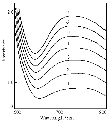 |
Fig.3 In situ visible spectra of polymerization of aniline, the solution consisting of 0.2 mol dm-3 aniline and 0.1mol dm-3 ferric sulfate. Curves: (1) first measurement, (2) second measurement, (7) seventh measurement. |
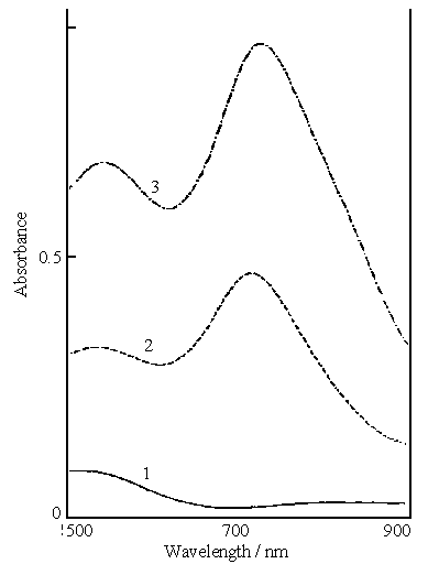 |
Fig.4 Visible spectra of filtrates from the reaction mixture of 0.2 mol dm-3 aniline, 0.1 mol dm-3 ferric sulfate and a given concentration of sulfuric acid. Curves : (1) 0.2, (2) 0.4, (3)0.6 mol dm-3 |
The comparison of the
absorbance at the same scan time in the above plots indicates that the starting
polymerization rate of aniline in the solution containing 0.2 mol dm-3 aniline
and 0.1 mol dm-3 ferric sulfate with pH 1.14 is the most quick one among the
three kinds of the solutions. This is mainly attributed to the protonation of aniline. The
degree of protonation increases with the increase of the concentration of acid. Thus, the
degree of protonation of aniline is the most weak one in 0.1 mol dm-3 ferric
sulfate solution of pH 1.14 and the strongest in 0.6 mol dm-3 sulfuric acid
among the solutions used. The stronger the protonation is, the more difficult the aniline
oxidation is. Therefore, the starting polymerization rate of aniline in 0.1 mol dm-3
ferric sulfate with pH 1.14 is the most quick one among the three kinds of the solution
used. The pH measurement shows that the pH increased from 1.14 to 1.28 after aniline was
added into 0.1 mol dm-3 ferric sulfate solution with stirring, and then the pH
of the solution decreased as the reaction proceeded. The former result is an evidence for
the protonation of aniline. The latter result indicates that aniline lost protons during
the polymerization process.
2.2 Conditions and evidence for "green" synthesis of polyaniline
After polymerization for 30 h, the mixture was filtered. Curve 1 in Fig.4 shows the
visible spectrum of the filtrate from the reaction mixture of 0.2 mol dm-3
aniline, 0.1 mol dm-3 ferric sulfate and 0.2 mol dm-3 sulfuric acid
(mixture A). There is only a absorption band between 560 to 500 nm with a much lower
absorbance of this curve . This indicates that there was a little water -soluble
polyaniline in the filtrate. The filter cake polyaniline was washed with the sulfuric acid
solution of pH 2. The filtrate of the washing solution was rather clear, so polyaniline
synthesized in this manner can be easily separated from the mixture, and almost did not
bring environmental pollution.
Curve 2 in Fig.4 shows the visible spectrum of the filtrate from the
reaction mixture of 0.2 mol dm-3 aniline, 0.1 mol dm-3 ferric
sulfate and 0.4 mol dm-3 sulfuric acid(mixture B). It is clear that there are
two peaks at 540 and 714 nm, the latter is attributed to polyaniline with the peak at 720
nm in Fig.s 1 and 2. Polyaniline at 540 nm was gradually formed as the reaction proceeded,
it has a shorter conjugation chain than that at 720 nm in Figs.1 and 2. The absorbances
for both peaks of curve 2 are much higher than that of curve 1. The color of this filtrate
was blue-violet. Curve 3 in Fig.4 shows the visible spectrum of the filtrate from the
reaction mixture of 0.2 mol dm-3 aniline, 0.1 mol dm-3 ferric
sulfate and 0.6 mol dm-3 sulfuric acid(mixture C). Curve 3 is very similar in
the shape to curve 2, but the absorbances of both peaks on curve 3 are higher than those
on curve 2. The color of this filtrate was dark blue-violet. From above results, we can
conclude that the color of the filtrate was caused by the concentration of the acid used
for the polymerization of aniline, its color intensity increased with increasing acid
concentration.
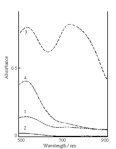
Fig.5 Visible spectra of washing solutions after washing polyaniline synthesized
in the solution. Curves (1) and (2) consisting of 0.2 mol dm-3 aniline, 0.1 mol
dm-3 ferric sulfate and 0.4 mol dm-3 sulfuric acid. Curves (3) and
(4) consisting of 0.2 mol dm-3 aniline, 0.1 mol dm-3 ferric sulfate
and 0.6 mol dm-3 sulfuric acid. Curves (1) and (3) for the first washing.
Curves (2) and (4) for the second washing.
After filtration , the collected polyaniline
was washed with sulfuric acid solution of pH 2. The visible spectra of the washing
solutions were measured. Curves 1 and 2 in Fig.5 show the visible spectra of the washing
solutions after the first and second washing polyaniline, respectively. The washing
solution in this case was used for washing polyaniline synthesized in the reaction mixture
B. The results from curves 1 and 2 indicate that the peak at 714 nm almost disappears on
curve 1, and only the peak at 540 nm remains. The latter absorbance decreases markedly
with washing time. In fact, the second washing solution is near colorless.
Curves 3 and 4 in Fig.5 show the visible spectra of the washing
solutions after the first and second washing , respectively. The washing solution in this
case was used for washing polyaniline obtained from the reaction mixture C. There are
still two peaks on curve 3, however only the peak at 540 nm remains on curve 4 and its
absorbance is much lower than that on curve 3. This means that the concentration of the
polymer with 520 nm in the washing solution was decreased with washing time and no polymer
with 720 nm remained in the second washing solution.
The results based on Fig.s 4 and 5 indicate that the solubility of
polyaniline synthesized at different concentrations of the acid increases with the
increase of acid concentration. Therefore, the solution consisting of 0.2 mol dm-3
aniline, 0.1 mol dm-3 ferric sulfate and 0.2 mol dm-3 sulfuric acid
is suitable for the "green" synthesis of polyaniline.
The visible spectra of polyaniline polymerized on ITO conducting glass
were measured. Polyaniline was synthesized in the solutions of 0.2 mol dm-3
aniline and 0.1 mol dm-3 ferric sulfate with 0.2, 0.4 and 0.6 mol dm-3
sulfuric acid. There is only a absorption peak around 730 nm (omitted here)for each
polyaniline sample. This means that polyaniline with the peak at 520 nm dissolved
completely in water, so it was easily removed by washing.
A separate experiment was carried out with ammonium peroxydisulfate as
oxidant to prepare polyaniline. Aniline in the solution containing each 0.2 mol dm-3
of aniline, ammonium peroxydisulfate and sulfuric acid was almost completely polymerized
in 1 h, so its polymerization rate is much faster than that with ferric sulfate as
oxidant. The yield of the polyaniline prepared in this manner is higher than that prepared
with Fe2(SO4)3 as oxidant. The latter is depending on
reaction time because of low polymerization rate. However, this filtrate from the reaction
mixture was dark blue-violet. It is clear that the color of this filtrate is mainly caused
by the polymerization rate, since the concentration of sulfuric acid was also 0.2 mol dm-3
. This indicates that the high polymerization rate readily results in producing
water-soluble polyaniline.
To prove further the relationship between polymerization rate and
formation of water-soluble polyaniline, the reaction mixture A was used for the
polymerization at 80 oC. The polymerization rate of aniline at 80 oC
was faster than at 15 oC based on the change in the color of the solution. The
color of the filtrate of the reaction mixture at 80 oC was blue-violet. This is
also evidence for the effect of polymerization rate on the formation of water-soluble
polyaniline. Of course, the filtrate color in this case partly came from the increase of
solubility of polyaniline. Based on the determination of molecular weight, the molecular
weight of polyaniline synthesized at low temperatures(0 to -30 oC)[12,20]
is higher than that synthesized at room temperature. This indicates that the lower
polymerization rate favors the formation of high molecular weight polyaniline, since the
polymerization rate decreases with the decrease of reaction temperature. Thus, we can
conclude that the solubility of high molecular weight polyaniline in water is less than
that of low molecular weight polyaniline, because the color of the filtrate from the
reaction mixture at 80 oC is much more intense than that at 15 oC as
described previously .
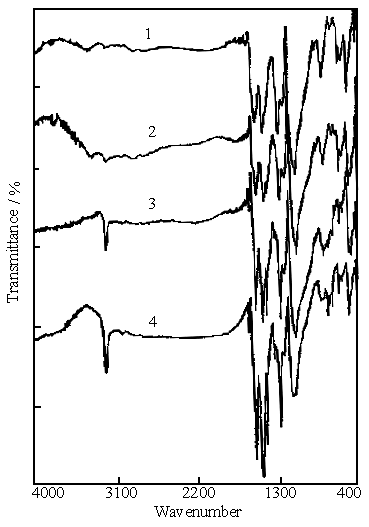
Fig.6 IR spectra of polyaniline synthesized in the solution consisting of 0.2 mol
dm-3 aniline, 0.1 mol dm-3 ferric sulfate with a given concentration
of sulfuric acid. Curves: (1) pH 1.14 (in the absence of sulfuric acid), (2) 0.2 mol dm-3,
(3) 0.4 mol dm-3, (4) 0.6 mol dm-3.
2.3 Conductivity of polyaniline
The conductivity of polyaniline synthesized in the solution of 0.2 mol dm-3
aniline and 0.1 mol dm-3 ferric sulfate is 0.84 S cm-1 . The
conductivities of polyaniline synthesized in the solutions of 0.2 mol dm-3
aniline and 0.1 mol dm-3 ferric sulfate with 0.2 ,0.4 and 0.6 mol dm-3
sulfuric acid are 2.3, 2.7 and 3.4 S cm-1, respectively. This means that the
conductivity of polyaniline increases with increasing the concentration of sulfuric acid
used for the polymerization of aniline.
To understand the effects of oxidants on the conductivity of
polyaniline, ammonium peroxydisulfate was used for oxidant . The solution used for the
polymerization consisted of each 0.2 mol dm-3 of aniline, ammonium
peroxydisulfate and sulfuric acid. The temperature was also controlled at 15 oC.
The conductivity of polyaniline synthesized in this manner is 3.8 S cm-1, which
is a little larger than those of polyaniline synthesized using ferric sulfate as oxidant.
2.4 IR spectra of polyaniline
Figure 6 shows the IR spectra of polyaniline samples, which were synthesized in the
solution of 0.2 mol dm-3 aniline and 0.1 mol dm-3 ferric
sulfate(curve 1), in the reaction mixture A(curve 2), in the reaction mixture B (curve 3)
and in the reaction mixture C (curve 4). The peak at 3232 cm-1 on each curve is
attributed to the N-H stretching vibrations. It is clear that its intensity increases with
the increase of the concentration of sulfuric acid , i.e., its intensity is very sensitive
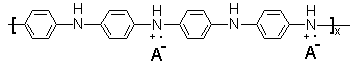
to the concentration of sulfuric acid. Polyaniline has the general composition[21]:
The increase in the intensity of the peak at 3232 cm-1 means that the number of the N-H bond in polyaniline composition increased with the increase of the concentration of sulfuric acid , in other words, polyaniline was gradually converted to emeraldine salt with conductivity of 2 to 5 S cm-1[22].
This is likely to be coincident with the measurement of conductivity mentioned above, in which the conductivity of polyaniline synthesized in the solution of 0.2 mol dm-3 aniline and 0.1 mol dm-3 ferric sulfate is the lowest, and the conductivity of polyaniline synthesized in the solution of 0.2 mol dm-3 aniline, 0.1 mol dm-3 ferric sulfate and 0.6 mol dm-3 sulfuric acid is the highest among the four samples.
The peaks at 1563 and 1478 cm-1 on curve 1 are attributed to quinone and benzene ring deformation[23], which are present in the samples of polyaniline synthesized by chemical polymerization of aniline using ammonium peroxydisulfate[23] as oxidant and enzyme-catalyzed polymerization in the presence of hydrogen peroxide[16], and the electrochemical polymerization of aniline in aqueous acidic solutions[24]. Their positions are independent of doped or dedoped forms of polyaniline[23,24]. However, the two peaks in Fig.6 are gradually split to three peaks with increasing concentration of the acid used for the polymerization of aniline. Their peak positions are at 1570,1492 and 1443 cm-1. The latter two peaks are attributed to the benzene ring deformation[23]. This means that the number of benzene ring in polyaniline composition could be increased. The increase in the number of benzene ring must result in increase of the number of N-H bond in polyaniline composition, which has been explained above. Therefore, the above results appear to be evidence for conversion of emeraldine base into emeraldine salt or conversion of different oxidation states of polyaniline[21,22].
The peak at 1105 cm-1 in Fig.6 is attributed to SO42-. This indicates that the samples of polyaniline synthesized at different concentrations of sulfuric acid all contained SO42-, which were doped into polyaniline during the polymerization process.
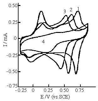 |
Fig.7 Cyclic voltammograms of polyaniline synthesized in the solution consisting of 0.2 mol dm-3 aniline, 0.1 mol dm-3 ferric sulfate and 0.6 mol dm-3 sulfuric acid. Cyclic voltammograms were carried out in 0.5 mol dm-3 Na2 SO4 solution with various pH values. Curves: (1) pH 1.0, (2) pH 2.0, (3) pH 3.0, (4) pH 4.0. |
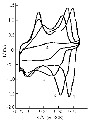 |
Fig.8 Cyclic voltammograms of polyaniline synthesized in the solution consisting of 0.2 mol dm-3 aniline, 0.1 mol dm-3 ferric sulfate and 0.4 mol dm-3 sulfuric acid. Cyclic voltammograms were carried out in 0.5 mol dm-3 Na2 SO4 solution with various pH values. Curves: (1) pH 1.0, (2) pH 2.0, (3) pH 3.0, (4) pH 4.0. |
2.5 Cyclic voltammograms of
polyaniline
The cyclic voltammetry of polyaniline synthesized at
different concentrations of sulfuric acid was carried out in 0.5 mol dm-3 Na2SO4
with different pH values. Figure 7 shows the cyclic voltammograms of polyaniline
synthesized in the reaction mixture C. It is clear that there are two oxidation and two
reduction peaks on the cyclic voltammogram of polyaniline at pHs 1.0, 2.0, and 3.0. The
redox peaks at higher positive potentials shift towards the negative potentials with
increasing pH. The redox peaks at lower potentials are slightly affected by pH value, but
their anodic and cathodic peaks shift slightly towards more positive and more negative
potentials at pH 3.0, respectively. This is caused by decrease in the conductivity of
polyaniline. The pH dependence of polyaniline here is similar to that of polyaniline
synthesized using ammonium peroxydisulfate[25] and electrochemical method[26].
The redox peaks in Fig. 7 almost disappear at pH 4.0. This means that the electrochemical
activity of polyaniline decrease with increasing pH value. Figure 8 shows the cyclic
voltammograms of polyaniline synthesized in the reaction mixture B , their wave shape and
pH dependence are similar to those shown in Fig.7.
Figure 9 shows the cyclic voltammograms of polyaniline synthesized in
the reaction mixture A. Compared with Fig.7 and Fig.8, an additional oxidation and
reduction peaks at the most positive potentials are observed in Fig.9, but the pH
dependence of the peak potentials is analogous to those in Fig.7 and Fig.8.
Figure 10 shows the cyclic voltammograms of polyaniline synthesized in
the solution of 0.2 mol dm-3 aniline and 0.1 mol dm-3 ferric
sulfate. The cyclic voltammograms at different pH values are similar to those shown in
Fig.9, but the additional oxidation and reduction peaks become more prominent than those
in Fig.9.
The above cyclic voltammograms (in Fig. 9and 10) of polyaniline at pH
1.0 to pH 3.0 show that the most positive potential of the additional redox peak is about
50 mV higher than those of polyaniline synthesized in the same solution(in Fig.7 and 8)
with the concentrations of sulfuric acid higher than 0.4 mol dm-3 , and
synthesized normally[25,26]. The additional redox peak shifts towards the
negative potentials with increasing pH as well as polyaniline synthesized normally, i.e.,
two pairs of redox peaks shift towards the negative potentials with increasing pH value in
Fig.s 9 and 10. This indicates that there are two forms of nitrogen atom in the
polyaniline composition, since protonation and deprotonation were carried out via nitrogen
atoms in polyaniline. The two forms of nitrogen atom in polyaniline were proposed by
MacDiarmid and Epstein[21,22] . This suggestion has been identified by XPS
spectra[27]. However, electrochemical evidence for this is only the first time.
This is because the synthesis of polyaniline presented here was carried out using weaker
oxidant. We must point out that a few papers reported that there are three pairs of the
redox peaks on the cyclic voltammograms of polyaniline at pH lower than 3, but in which
the additional redox peak is very small and broad, and located about midway between two
pairs of the redox peaks[28,29], which is much different from those shown in
Fig.s 9 and 10.
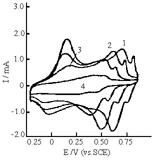 |
Fig.9 Cyclic voltammograms of polyaniline synthesized in the solution consisting of 0.2 mol dm-3 aniline, 0.1 mol dm-3 ferric sulfate and 0.2 mol dm-3 sulfuric acid. Cyclic voltammograms were carried out in 0.5 mol dm-3 Na2 SO4 solution with various pH values. Curves: (1) pH 1.0, (2) pH 2.0, (3) pH 3.0, (4) pH 4.0. |
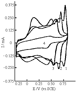 |
Fig.10 Cyclic voltammograms of polyaniline synthesized in the solution consisting of 0.2 mol dm-3 aniline, 0.1 mol dm-3 ferric sulfate . Cyclic voltammograms were carried out in 0.5 mol dm-3 Na2 SO4 solution with various pH values. Curves: (1) pH 1.0, (2) pH 2.0, (3) pH 3.0, (4) pH 4.0. |
3. CONCLUSION
The conductivity of polyaniline synthesized with ferric sulfate as oxidant is very close
to that synthesized with ammonium peroxydisulfate as oxidant. The polymerization of
aniline with ferric sulfate as oxidant and polyaniline synthesized in this way contain a
wealth of information about growth and composition of polyaniline. Visible spectra for the
polymerization process of aniline and the filtrate after polymerization of aniline
indicate that polyaniline with the peak at 520 nm completely dissolved in water, and
polyaniline with the peak at 720 nm has a small solubility in water, depending on the
concentration of sulfuric acid used for the polymerization of aniline. The Changes in the
intensity of the peak for N-H bond and the splitting of the absorption band between 1563
and 1478 cm-1 in the IR spectra of polyaniline and an additional redox peak at
most positive potentials on the cyclic voltammograms of polyaniline are related to the
interconversion between benzene and quinone rings, and the change of N-H bond number in
polyaniline. This relationship is likely to be evidence for the interconversion between
emeraldine base and emeraldine salt, or interconversion of different oxidation states of
polyaniline, and reveals the complexity of polyaniline composition. The color of the
filtrate from the reaction mixture is caused by the concentration of sulfuric acid used
for the polymerization of aniline and polymerization temperature. The latter is
essentially related to the molecular weight of polyaniline. A tremendous advantage for the
polymerization of aniline with ferric sulfate as oxidant is that "green"
synthesis of polyaniline can be carried out, the conditions for which are that
the solution for the polymerization consisted of 0.2 mol dm-3 aniline ,0.1 mol
dm-3 ferric sulfate and 0.2 mol dm-3 sulfuric acid, and the
temperature was controlled below 15oC.
REFERENCES
[1] MacDiarmid A G, Mu S L, Somasiri N L D et al. Mol.
Cryst. Liq. Cryst., 1985, 121: 187.
[2] Novak P, Muller K, Santhanam K S V et al. Chem. Rev., 1997,
97: 207.
[3] Kobayashi T, Yonevama N, Tamura H. J. Electroanal. Chem., 1984,
177: 281.
[4] Batich C D, Laitinen H A, Zhou H C. J. Electrochem. Soc., 1990, 137: 883.
[5] Desilvestro J, Hass O. J. Chem. Soc. Chem. Commun., 1985, 346.
[6] Dong Y H, Mu S L. Electrochim. Acta., 1991, 36: 2015.
[7] Karg S, Scott J C, Salem J R et al. Synth. Met., 1996, 80: 111.
[8] Bartlett P N, Whitaker R G. Biosensor, 1987/88, 3: 359.
[9] Yang Y F, Mu S L. J. Electroanal. Chem., 1997, 432: 71.
[10] MacDiarmid A G, Chiang J H, Halpern M et al. Mol. Cryst. Liq. Cryst., 1985, 121: 173.
[11] Tzou K, Gregory R V. Synth. Met., 1992, 47: 267.
[12] Adams P N, Laughlin P J, Monkman A P. Synth. Met., 1996, 76: 157.
[13] Chan H S O, Ho P K H, Tan K L et al. Synth. Met., 1990, 35: 333.
[14] Genies E M, Tsintavis C, Syed A A. Mol. Cryst. Liq. Cryst.,
1985,121:181.
[15] Inoue H, Kida Y, Imoto E. Bull. Chem. Soc. Jpn., 1966, 39: 551.
[16] Liu W, Kumar J, Tripathy S et al. J.Am. Chem. Soc., 1999, 121: 71.
[17] Bacon J, Adams R N. J.Am. Chem. Soc., 1968, 90: 6596.
[18] Yang H, Bard A J. J. Electroanal. Chem., 1992, 339: 423.
[19] Mu S L, Kan J Q. Electrochim. Acta,1996, 41:1593.
[20] Mattoso L H C, MacDiarmid A G, Epstein A J. Synth. Met., 1994, 68:1.
[21] MacDiarmid A G, Manohar S K, Masters J G et al. Synth. Met., 1991, 41-43: 621.
[22] Avlyanov J K, Min Y G, MacDiarmid A G et al. Synth. Met., 1995, 72: 65.
[23] Tang J S, Jing X B, Wang B C et al. Synth. Met., 1988, 24: 231.
[24] Mu S L, Kan J Q. Synth. Met., 1998, 98: 51.
[25] Wang W S, Humphrey B D, MacDiarmid A G. J. Chem. Soc, Faraday Trans. I., 1986, 82:
2385.
[26] Inzelt G, Horanyi G. Electrochim. Acta, 1990, 35: 27.
[27] Kang E T, Neoh KG, Tan K L. Surface and Interface Analysis, 1993, 20: 833.
[28] Dhawan S K, Trivedi D C. J. Appl. Electrochem., 1992, 22: 563.
[29] Mu S L, Kan J Q. Synth. Met., 1998, 92: 149.