http://www.chemistrymag.org/cji/2004/061004pe.htm |
Jan.3, 2004 Vol.6 No.1 P.4 Copyright |
Detailed kinetics of the Fischer-Tropsch synthesis over an industrial Fe-Mn catalyst during early period of reaction
Yang Jun 1, Liu Ying1,2, Zhang Yuanming1, Tang Yu1(1Department of Chemistry, Jinan University, Guangzhou 510632, China; 2State Key Laboratory of Coal Conversion, Institute of Coal Chemistry, Chinese Academy of Sciences, Taiyuan 030001, China)
Received on Nov. 2, 2003; Support by the Committee of Science and Technology of China (No.2001AA523010)
Abstract The detailed kinetics of Fischer-Tropsch synthesis (FTS) over an industrial Fe-Mn catalyst during early period of reaction (200 h Time on stream (TOS)) was studied in a continuous fixed bed reactor under operation conditions of the low temperature and low H2/CO ratio. 39 combined kinetic models of FTS based on the LHHW type mechanism were scanned with non-linear regression method. The conclusion in this work is consistent with that obtained in our previous work under higher reaction temperature and H2/CO ratio of syngas. The FTS model based on alkylidene mechanism could produce a good fit of experimental data. In this work, the estimated activation energy for chain growth is 60.55 kJ.mol-1, which is lower than that of our previous study (75.52kJ.mol-1), indicating that the energy barrier for the chain growth is lower for the catalyst with shorter TOS. This can well interpret the trend to higher selectivity of the lower molecular hydrocarbon, especially the methane, with longer TOS observed in our previous work, which probably results from phase change of catalyst in the course of the synthesis reaction.Keyword Fischer-Tropsch synthesis, Fe-Mn catalyst, Kinetics
1. INTRODUCTION
Fischer-Tropsch synthesis (FTS) as an alternate method for synthesizing liquid fuels
and chemical feed-stocks from syngas derived from coal, natural gas, and other carbon
sources, has drawn renewed attention in recent years.[1,2] FTS produces a
mixture of hydrocarbons and oxygenates, and the hydrocarbons are the main products, which
range from methane to heavy wax.[3] Therefore, the critical problem of the FTS
is the control of product selectivity. For this purpose, the FTS kinetics on the basis of
a detailed mechanism is urgently needed. The kinetics of the FTS with iron-based catalysts
has extensively been studied by many investigators.[3-8] In 1988 Wojciechowski,[8]
and recently van der Laan[3] had given detailed literature reviews about the
FTS kinetics and mechanisms developed in last decades. However, in most cases, the
hydrocarbon products were lumped according to the carbon number of the hydrocarbon
molecules with an ideal Anderson-Schulz-Flory (ASF) distribution, and only a few of them
were based on the LHHW and ER type mechanisms. With those kinetics models, the deviations
from the conventional ASF distribution reported by many researchers,[9,10] cannot
be described and explained.
In van der Laan's work, [3] the deviations from the ideal
ASF distribution can be described with their model. However, the model of product
distribution and the reactant consumption kinetics were treated separately. The
experiments in both cases were carried out by keeping temperature constant, and the effect
of the temperature on the performance of catalyst was not considered in their kinetic
models. Zimmerman and Bukur[11] proposed a kinetic model, in which the
re-adsorption and secondary reaction of the 1-olfins was considered. With this model, the
increase of the paraffin/olefin ratio with carbon number can be predicted. However, there
are significant deviations between the mole fractions of hydrocarbon predicted and those
of experiment, especially for methane and ethene. In 1993, Lox and Froment[4,5]
developed several kinetic models over a commercial precipitated iron catalyst, in which
the rates of reactant consumption and the linear hydrocarbon formation were unified. In
their work, the kinetic experiments were carried out in a wide range of operation
conditions. However, the readsorption and secondary reaction of olefins are not considered
and the deviations from the conventional ASF distribution reported in many literature
cannot be described.[9,10] Very recently, we have proposed a systematic
approach for considering more complicated olefin re-adsorption phenomenon in kinetic
modelling over a precipitated iron catalyst. The predicted product distribution fitted
well with the experimental data over an industrial Fe-Cu-K catalyst in a fixed bed
reactor. However, this model is not suitable for the Fe-Mn catalyst.
In 1990s, the industrial Fe-Mn catalyst, which was prepared by
Institute of Coal Chemistry (ICC), Chinese Academy of Sciences, was tested at pilot-scale
level with a syngas of H2/CO=2.0 in a fixed bed reactor. The experimental
results showed that this catalyst was highly active and stable. From the fundamental and
practical standpoints, it is desirable to obtain a kinetics model based on detailed
mechanism, which is valid over a wide range of operation conditions and can describe the
conversions of the reactants and the product distribution simultaneously.
In our previous work, 13 kinetic models of the FTS reaction and 3
models of the water-gas shift (WGS) reaction has been constructed for the Fe-Mn catalyst
on the basis of the LHHW and ER mechanisms.[12] The 39 FTS kinetic models were
scanned by firstly genetic algorithm(GA) and secondly conventional Levenberg-Marquardt(LM)
method for finding the "best" parameter values. The results showed that the FTS model on the
basis of the alkylidene mechanism and the WGS model based on formate intermediate
mechanism can describe both the distribution of paraffins and olefins and the consumption
rates of the reactants well. However, the range of the operation conditions employed in
the kinetic experiments is still not wide enough and the effect of time-on-stream (TOS) on
kinetics is not considered. The present work is to develop the FTS kinetics that can
self-consistently describe the hydrocarbon distribution and the reactant consumption over
the Fe-Mn catalyst. In order to study the effect of TOS on catalytic performance and the
kinetics of catalyst, in this paper, the experiments are carried out during the different
reaction periods from previous work and with a more wide range of operation conditions.
2. EXPERIMENTAL SECTION
4.01 g (3cm3) catalyst
particles in the diameter of 0.18-0.25 mm (60-80 ASTM mesh), was packed in a fixed bed
reactor with a length of 1.0 m and an internal diameter of 0.012 m. The catalyst had a
composition of Fe-Mn (atomic ratio of Fe/Mn =3) and 1% of K2O, and a BET
surface area of 117.8 m2/g. Prior to reaction, the catalyst was activated at
548K, 0.25-0.30MPa, 1000 h-1 with syngas of 2.0 (H2/CO) ratio for 36
h. After the activation, the temperature was adjusted to desired reaction temperature. In
this work, the catalyst was initially treated at 523 K under FTS reaction conditions with
syngas for 200 h to ensure
3. RESULTS AND DISCUSSION
3.1 Experimental results
The experiments results are given in Table 3. An orthogonal composite experimental design was used to arrange temperature, pressure and H2/CO ratio for all experiments, enabling efficient and optimal distribution of experiment points. Finally, 26 experimental points, which include 16 orthogonal points (according to an orthogonal table of L16 (43)) and 10 additional points were applied for the kinetic studies. One point (point 15 in Table 3) is used as reference point (point 12 in Table 3) to check for deactivation and reproducibility of the experimental data. The results show that the conversion of reactants at No. 15 well reproduced those at No.12, indicating that the catalyst did not suffer permanent deactivation during the course of kinetic experiments and catalytic phase had reached a relatively stable state. Table 1 Experimental conditions and results
Run |
T/K |
P/MPa |
H2/CO ratio |
Fin |
Reaction Time |
CO conversion |
H2 conversion |
Fexit |
oil/g |
Wax/g |
Water/g |
1 |
523.0 |
1.00 |
0.67 |
150.6 |
13.17 |
16.12 |
14.63 |
131.1 |
0.58 |
1.96 |
1.67 |
2 |
523.0 |
1.00 |
0.67 |
102.5 |
23.00 |
20.51 |
21.61 |
84.9 |
0.86 |
2.63 |
2.53 |
3 |
523.0 |
1.50 |
1.01 |
150.5 |
17.83 |
23.66 |
21.16 |
123.0 |
1.37 |
3.76 |
5.19 |
4 |
523.0 |
2.00 |
1.50 |
151.3 |
13.50 |
39.13 |
28.46 |
110.4 |
1.66 |
4.58 |
5.66 |
5 |
523.0 |
2.50 |
2.02 |
150.1 |
12.83 |
54.41 |
34.27 |
97.7 |
3.46 |
4.79 |
8.37 |
6 |
533.0 |
1.00 |
1.00 |
200.4 |
12.00 |
15.69 |
14.45 |
177.7 |
1.32 |
1.41 |
3.41 |
7 |
533.0 |
1.50 |
0.67 |
200.6 |
12.00 |
19.53 |
18.84 |
170.3 |
1.26 |
2.53 |
3.18 |
8 |
533.0 |
2.00 |
2.02 |
200.2 |
12.00 |
53.68 |
34.41 |
135.8 |
2.39 |
4.19 |
8.04 |
9 |
533.0 |
2.50 |
1.51 |
200.4 |
12.50 |
52.29 |
38.43 |
129.1 |
2.84 |
5.23 |
7.36 |
10 |
533.0 |
1.50 |
2.02 |
200.2 |
12.00 |
41.00 |
25.57 |
150.3 |
2.25 |
2.12 |
6.80 |
11 |
543.0 |
1.00 |
1.50 |
250.4 |
12.58 |
25.81 |
17.98 |
211.5 |
2.18 |
1.11 |
4.99 |
12 |
543.0 |
1.50 |
2.03 |
250.1 |
12.25 |
50.79 |
29.11 |
178.0 |
3.21 |
1.49 |
8.03 |
13 |
543.0 |
2.50 |
1.00 |
250.5 |
12.17 |
40.17 |
34.50 |
180.4 |
3.49 |
6.08 |
6.98 |
14 |
543.0 |
2.00 |
0.67 |
249.9 |
12.67 |
28.92 |
25.24 |
201.4 |
2.44 |
4.17 |
5.05 |
15 |
543.0 |
1.50 |
2.03 |
250.1 |
18.83 |
48.99 |
27.47 |
182.8 |
4.93 |
2.25 |
12.18 |
16 |
553.0 |
1.00 |
2.00 |
300.1 |
13.33 |
43.19 |
19.66 |
244.7 |
2.78 |
0.79 |
6.57 |
17 |
553.0 |
1.50 |
1.50 |
301.3 |
12.18 |
46.38 |
28.76 |
227.5 |
4.08 |
1.63 |
7.74 |
18 |
553.0 |
2.00 |
1.00 |
300.6 |
12.17 |
40.62 |
32.21 |
222.9 |
4.79 |
2.87 |
8.06 |
19 |
553.0 |
2.50 |
0.67 |
250.8 |
11.00 |
44.23 |
43.79 |
172.9 |
3.84 |
5.57 |
5.27 |
20 |
553.0 |
1.00 |
2.01 |
350.0 |
12.00 |
36.23 |
17.21 |
296.3 |
2.32 |
0.63 |
5.92 |
21 |
563.0 |
2.00 |
1.51 |
350.3 |
12.00 |
73.58 |
42.96 |
216.2 |
7.70 |
2.70 |
10.87 |
22 |
563.0 |
1.50 |
1.00 |
300.6 |
12.75 |
45.89 |
33.71 |
220.7 |
5.36 |
1.78 |
5.97 |
23 |
563.0 |
1.00 |
0.67 |
200.7 |
12.00 |
25.36 |
17.18 |
172.8 |
1.99 |
0.81 |
1.27 |
24 |
563.0 |
2.50 |
2.00 |
450.9 |
11.70 |
80.05 |
40.93 |
278.3 |
7.77 |
3.03 |
16.94 |
25 |
563.0 |
2.50 |
2.00 |
601.7 |
12.02 |
66.63 |
35.41 |
404.3 |
9.17 |
2.76 |
22.05 |
26 |
563.0 |
2.00 |
1.50 |
400.3 |
11.81 |
68.42 |
39.98 |
258.5 |
7.32 |
2.52 |
11.92 |
Fin is the input flow velocity of reactants, Fexit is the flow velocity of tail gas.
3.2 Evaluation of the kinetics model
The FTS reaction system is very
complicated, which consist of a great number of reactions. Ten mechanisms
for the FTS reactions were constructed by assuming different chain initiation, propagation
and termination steps, one of them (FT III) is listed in Table 2, and the others are
presented elsewhere.[12]
Table 2 Elementary steps, and corresponding expressions of rates, and equilibrium
constants for FT reaction (Model FT III)
Step |
Elementary reaction |
expressions of rate and equilibrium constants |
1 |
CO + s1 ---------- COs1 |
|
2 |
COs1 +H2 ------- H2 CO s1 |
|
3 |
H2 CO s1 + H2 |
|
4 |
H2 + 2s1 ------ 2Hs1 |
|
5(n) |
CH2s1 + CH2s1 |
|
6(n) |
CnH2ns1 + Hs1----CnH2n+1 s1+ s1 |
|
7(n) |
CH3s1 + Hs1 ------CH4 + 2s1 |
|
CnH2n+1s1 + Hs1 |
|
|
8(n) |
CnH2ns1 ------CnH2n + s1 |
|
For model FT III, it is assumed that the rate determining steps are the chain growth by the insertion of methylene into the metal-alkydiene bond (step 5) and the desorption of the products (step 7, 8). The remaining steps are considered to be very rapid and at equilibrium. The formation rates of the hydrocarbons can be derived by assuming the concentrations of surface intermediates in the pseudo steady state condition, and this is described in detail in our previous work.[12] Finally, the rates expression of hydrocarbon formation for model FT III can be written as follows:
 (1)
(1)
 (2)
(2)
 (3)
(3)
where an represents the chain
growth factor for carbon number n (![]() ),
),
For different assumptions of the rate-determining step in WGS, the rate expressions of the CO2 of WGS reaction can be derived, the details are described in our previous work.12 Take model WGS3 as an example, it is assumed that the desorption of CO2 via formate intermediate (step IV) is slower than others in WGS, the remaining steps are at equilibrium, and the rate expression of CO2 formation can be derived as follows
 (4)
(4)
where ![]() represents
the rate constant of CO2 formation,
represents
the rate constant of CO2 formation, ![]() represents the equilibrium constant of the WGS reaction.
represents the equilibrium constant of the WGS reaction.
The accuracy of the model relative to the experimental data was
obtained from the MARR (mean absolute relative residuals) function:
 (5)
(5)
In this work, 39 models of
FTS are scanned by fitting the experimental data. The detail of model establishment and
kinetic equation derivation have been described elsewhere.[12] For scanning the
models by parameter optimization, several basic physical criteria are applied: the rate
constants and equilibrium constants should be positive, and the activation energies for
the paraffins and olefin formation and for WGS reaction should be in the range of values
reported by other researchers. The candidate models are estimated sequentially using the
genetic algorithm (GA) approach and the LM algorithm to search the "best"
parameter in the kinetic model. The methods of the parameter
estimation and the model discrimination are the same as that of previous work. [12]
21 kinetics models are rejected due to the unreasonable values of
parameters. The remained 18 rival models are evaluated sequentially by the comparison of
their mean absolute relative residuals (MARR) and F-test results. The result shows that
the MARR of most models are more than 30% except three of them. The three models are FT
III WGS3 (MARR 17.8%), FT VI WGS3 (MARR 21.5%), and FT VIII WGS 3 (MARR 24.8%).
Parameter |
value |
unit |
Parameter |
value |
unit |
||
Run A |
Run B |
Run A |
Run B |
||||
k5,0 |
9.37¡Á102 |
7.88 ¡Á103 |
mol.g-1.s-1.bar-1 |
Ev |
65.91 |
58.43 |
kJ.mol-1 |
E5 |
60.55 |
75.52 |
kJ.mol-1 |
k--8 |
5.50 ¡Á 10-5 |
2.77 ¡Á 10-5 |
mol.g-1.s-1.bar-1 |
k7M,0 |
6.96 ¡Á106 |
2.01 ¡Á106 |
mol.g-1.s-1.bar-1 |
Kv |
1.42 ¡Á 10-2 |
2.76 ¡Á10-2 |
bar-0.5 |
E7M |
100.04 |
97.39 |
kJ.mol-1 |
K1 |
9.46 |
2.59 |
bar-1 |
k7,0 |
2.0 ¡Á107 |
1.10 ¡Á106 |
mol.g-1.s-1.bar-1 |
K2 |
9.28 ¡Á10-4 |
1.67 ¡Á10-3 |
bar-1 |
E7 |
118.24 |
111.48 |
kJ.mol-1 |
K3 |
0.26 |
8.34 ¡Á10-2 |
¡¡ |
k8,0 |
6.45 ¡Á 104 |
8.79 ¡Á103 |
mol.g-1.s-1 |
K4 |
1.03 |
1.21 |
bar-1 |
E8 |
103.17 |
97.37 |
kJ.mol-1 |
K6 |
0.28 |
0.10 |
¡¡ |
kv,0 |
5.21 |
3.42 |
mol.g-1.s-1.bar-1.5 |
¡¡ | ¡¡ | ¡¡ | ¡¡ |
Reaction conditions of Run A, T: 523-563 K, H2/CO
ratio: 0.67-2.0, P: 1.0-2.5 MPa, space velocity: 2.2-8.6 l/g Cat h, after 200 h
time on stream.
Reaction conditions of Run B, T: 553-601 K, P: 1.0-3.0 MPa, H2/CO ratio: 1.0 -
3.0, space velocity: 5.9-15.4 l/g Cat h, after 1 000 h time on stream.
E5 is activation energy for chain growth (kJ.mol-1), E7M
is activation energy for methane formation (kJ.mol-1), E7
is activation energy for paraffin formation (kJ.mol-1), E8 is
activation energy for olefin formation (kJ.mol-1), Ev is
activation energy for WGS reaction (kJ.mol-1)
3.3 Discussions
The model FT III WGS3 fit well with the experimental data. This is consistent with
that of our previous work performed under higher temperature (553-601 K) and high H2/CO
ratio (1.0-3.0) after 1000 h TOS. The comparison of the parameters obtained in these two
kinetic tests, Run A (after 200 h TOS) and Run B (after 1000 h TOS), is presented in Table
3, and all of parameters are significantly different from zero.
In this work, the estimated activation energy for chain growth is 60.55
kJ.mol-1 (Run A), and is lower than that of Run B (75.52kJ.mol-1),
indicating a lower energy barrier for the chain growth with shorter TOS. The activation
energies for methane, olefin and paraffin formation are 100.14 kJ.mol-1, 118.24
kJ.mol-1, and 103.17 kJ.mol-1, respectively, which are slightly
different from those of Run B (97.39 kJ.mol-1, 111.48 kJ.mol-1, and
97.37 kJ.mol-1, respectively). The results show that the rates of the chain
growth, the methane, olefin and the paraffin formation of Run A are greater than those of
Run B, indicating that the catalysts in Run B suffered modest deactivation. The trend to
higher selectivity of the lower molecular hydrocarbon, especially the methane, observed in
previous work is probably attributed to the higher energy barrier for chain
growth during the later period of reaction (after 1000 h TOS ), which probably results
from phase change of the catalyst during the reaction. The shift in hydrocarbon
distribution towards lower molecular hydrocarbon with catalyst aging has also been
observed in several other studies with iron catalyst.[13-14]
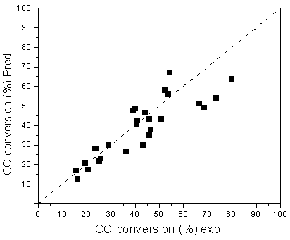
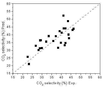
The comparison between the experimental and the predicted values of
conversion of CO, selectivity of CO2 are presented in Figures 1&2. The
results show that the relative residuals between the model predicted and experimental are
mostly within 20%.


Figure 1. Experimental and predicted CO conversions
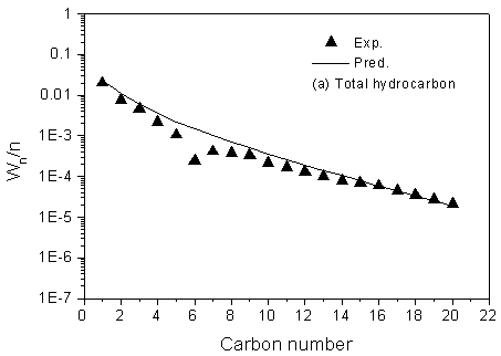
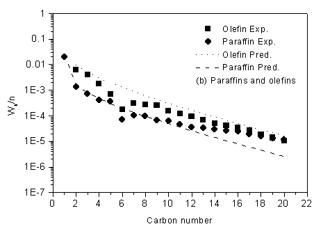
The simulation was run under the same conditions as it was employed during the kinetic experiment. The comparison of experimental and predicted product distribution are presented in Figure 3. The results show that the modeled product distributions of total hydrocarbon using FT III WGS3 are in an excellent agreement with the experimental selectivity, and the deviation for methane is described fairly accurately.

Figure 2. Experimental and predicted CO2 selectivities

Figure 3 Prediction of
product distribution
Reaction condition: T=543.0K, P=2.0MPa, H2/CO=0.67, GHSV=3.7 l(STP)/g-cat·h
4. CONCLUSION
FTS kinetics experiments over an industrial Fe-Mn UFP catalyst are carried out during
the different reaction periods for a wide range of industrially relevant conditions. Based
on different LHHW and ER type mechanisms for the FTS reactions and the WGS reaction, 39
models for FT synthesis were constructed. The rival models were used to fit the
experimental data sequentially by global parameter optimization. The result is consistent
with our previous finding, namely the model based on alkylidene mechanism for the FTS
gives a good fit of the experimental data. The estimated activation energy for chain
growth in this work is 60.55 kJ·mol-1, which is lower than that of our previous
study (75.52kJ.mol-1), indicating that the energy barrier for the chain growth
is lower for the catalyst with shorter TOS. This can well interpret the trend to higher
selectivity of the lower molecular hydrocarbons, especially the methane, with increasing
of TOS observed in our previous work, which probably results from phase change of catalyst
in the course of the synthesis reaction.
REFERENCES
[1] Dry M E. Catal. Today, 2002, 71: 227.
[2] Dry M E. Appl. Catal. A: General., 1996, 138: 319.
[3] Van der Laan, G, Beenackers, A. A. C. M., and the literatures herein.
[4] Lox E S, Froment G F. Ind. Eng. Chem. Res., 1993, 32: 61.
[5] Lox E S, Froment G F. Ind. Eng. Chem Res., 1993, 32: 71.
[6] Wang Y N, Ma W P, Lu Y J et al. Fuel., 2003, 82:195.
[7] Zimmerman W H, Bukur D B. Can. J. Chem. Eng., 1990, 68: 292.
[8] Wojchiechowski B W. Catal. Rev. Sci. Eng., 1988, 30: 629.
[9] Satterfield C N, Huff G A. J. Catal., 1982, 73:187.
[10] Kuipers E W, Vinkenburg I H, Oosterbeek H. J. Catal., 1995, 152: 137.
[11] Zimmerman W H, Bukur D B, Ledakowicz S. Chem. Eng. Sci., 1992, 47: 2707.
[12] Yang J, Liu Y, Chang J. et al. Ind. Eng. Chem. Res., 2003, 42 (2): 5066.
[13] Bukur D B, Patel S A, Lang X S. Appl. Catal., 1990, 61: 329.
[14] Donnelly T J, Satterfield C N. Appl. Catal., 1989, 52: 93.

