| http://www.chemistrymag.org/cji/2006/08b070pe.htm | Nov. 9,
2006 Vol.8 No11 P.70 Copyright |
Zhai
Yongqing, Meng Yuan, Cao Lili, Zhou Jian
(College of Chemistry and Environmental Science, Hebei University, Baoding 071002, China)
Received Oct. 16, 2006.
Abstract Long afterglow photoluminescent
materials Sr2-xCaxMgSi2O7 doped
with Eu2+,Dy3+ were prepared by gel-combustion method.The synthesized samples were characterized by X-ray diffraction and
SEM. The excitation spectrum, emission spectrum and long decay curve were measured and
analyzed. XRD patterns indicate that the phosphors have tetragonal crystal structure. SEM
photographs show that the initial particles are very small
with diameter below 100nm. Both the emission and excitation spectra are broad-band
continuous spectrums. The main excitation peak is at about 400nm. With the increasing of
Ca(x=0,0.5,1,1.5,2) doped in Sr2-xCaxMgSi2O7,
the main emission peak shifts from 468nm to 483nm, 500nm, 512nm, 520nm respectively, the
photoluminescent color ranges from blue to blue-green, green, yellow-green, yellow. The
decay curves indicate that all of these phosphors have long afterglow features. Moreover,with the increasing of Ca doped in the host, the long afterglow
brightness and duration time decreases. It results from the slight change of
microstructure.
Keywords Sr2-xCaxMgSi2O7:Eu2+,Dy3+;
gel-combustion; long afterglow; luminescence
1. INTRODUCTION
Long-lasting phosphors are materials with long decay time, ranging from a few
minutes to tens of hours. These materials have received increasing interest in recent
years due to their extensive applications in many fields such as road signs, billboards,
graphic arts, interior decoration, etc[1,2]. Long lasting aluminate-based
phosphors attracted more research because of their excellent properties, such as no
radiation, high brightness and long afterglow. But the properties of these phosphors may
be decreased greatly while soaked in the water after several hours, thus limited their
application[3,4]. Alkaline earth silicates are useful luminescent hosts with
high physical and chemical stability. Poort et al. prepared Sr2MgSi2O7:Eu
and Ca2MgSi2O7:Eu phosphors by firing at 800oC in a reducing
atmosphere, and found that the main emission peaks located at 470 and 535 nm respectively[5].
But the long afterglow was not observed in these phosphors. Recently, Lin[6]
and Sabbagh Alvani[7] et al. prepared Eu2+, Dy3+ co-doped
Sr2MgSi2O7 phosphors through solid state reaction method,
and found these phosphors would emit a blue-green light peaking at 476 nm upon UV
illumination and show long afterglow. The blue-green emission is believed to be caused by
the 4f 5d transitions. The 4f electrons of Eu2+ are not sensitive to the
changes of the crystals field strength due to the shielding function of outer shell, the
5d electrons can split easily by these changes. Thus, the emission of 5d-4f from Eu2+
is strongly dependent on the host lattice.
In our present work, a series of alkaline earth silicates-based
phosphors Sr2-xCaxMgSi2O7:
Eu2+, Dy3+ with long
afterglow were prepared by gel-combustion method to obtain homogeneous products at
relatively low reaction temperature. The effect of doped Ca on the crystal structure,
photoluminescence and afterglow characteristics were examined and studied in detail.
2.1. Experimental process
The long afterglow phosphors were synthesized by gel-combustion method. SrNO3 (A.R), Mg(NO3)2·6H2O (A.R), Ca(NO3)2.4H2O (A.R), tetraethoxysilane(TEOS, A.R), anhydrous ethanol, Eu2O3(99.9%) and Dy2O3(99.9%) were employed as raw materials. Small quantities of H3BO3 (about 15mol% per mole of product) were added as flux. Urea (AR) was used as fuel.
The procedure used to prepare Sr2-xCaxMgSi2O7:Eu2+0.02,Dy3+0.04 is as follows. Firstly, Eu2O3 and Dy2O3 were dissolved in appropriate concentration of nitric acid to form nitrate solution, then the accurate concentration was determined by EDTA complexing titration to ensure a desired stoichiometry. According to the nominal composition of Sr2-xCaxMgSi2O7:Eu2+0.02,Dy3+0.04 (x=0,0.5,1,1.5,2), stoichiometric TEOS, SrNO3, Ca(NO3)2.4H2O, Mg(NO3)2·6H2O, Eu(NO3)3 and Dy(NO3)3 solutions were mixed in a 100ml crucible. Appropriate amounts of anhydrous ethanol, H3BO3, urea(1.5 times excess amounts of metal nitrates) and distilled water were added into it. The mixture was stirred to obtain a homogenous and transparent solution. Subsequently, a small amount of HNO3(1mol.L-1) was added as a catalyst and pH value of the solution was adjusted to 2-3. Next, the resulting solution was heated by water bath at 70-75oC for several hours to evaporate superfluous water, the volume of the solution decreased and the viscosity increased continuously because of gradual polymerization. When the volume of the solution could not decrease, the solution became a transparent gel. Then the gel was put into oven and dried at 85oC for 24h. The dry gel was ignited at 800oC in a muffle furnace under air atmosphere. This combustion process only required 1 min. The dry white sponge sample (which was called precursor) was formed. Due to the evolved gases, the apparent volume expanded after combustion and the precursor became so loose that it could be broken into fine pieces easily. Finally, the precursor was calcined in muffle furnace under an active carbon atmosphere at 1000oC for 75min to obtain the sample.
2.2 Characterization
Phases and crystallization of the samples were identified by X-ray diffraction analysis (XRD) with a Y2000 diffractometer using Cu-Ka radiation. The size and morphology of the samples were investigated with a KYKY 2800B scanning electron microscope (SEM). The excitation and emission spectrums of the samples were recorded as pellets on a RF-540 fluorescence spectrometer. The emission spectrum was measured at the excitation wavelength of 400nm. The decay curve of afterglow was measured by the ST-900PM brightness meter, and the samples were irradiated by the standard lamp for 15 min. All of the measurements were carried out at room temperature.
Fig. 1 XRD patterns of Sr2-xCaxMgSi2O7:
Eu2+0.02,Dy3+0.04
3. RESULTS AND DISCUSSION
3.1 XRD analysis of the obtained phosphors
XRD patterns of the samples are shown in Fig.1. When x=0.0, nearly all of the peaks
can be indexed to the Sr2MgSi2O7, which are in excellent
accord with powder data in JCPDS card( No.75-1736). According to that, the sample is
tetragonal crystalline Sr2MgSi2O7. With the increasing of
Ca (x=0,0.5,1,1.5,2), the peaks move slightly to the direction of big angle. The
reason is that the radius of Ca2+ (rCa) is a little smaller
than Sr2+(rSr), with the increase of concentration of Ca2+
in Sr2-xCaxMgSi2O7 (x=0,0.5,1,1.5,2),the cell parameters of Sr2-xCaxMgSi2O7
decrease, and interplanar distance decreases too. According to the Bragg equation, dsinq=l, where d is interplanar distance, q is Bragg angle, and l is radiation wavelength
(0.154178nm for Cu Ka),
Bragg angle increases with the decrease of d. When x=2.0, nearly all of the
peaks are consistent with powder data in JCPDS card(No.35-592). According to that, the
sample is tetragonal crystalline Ca2MgSi2O7. Therefore,
it can be seen that the 2q at each peak in the XRD patterns for Sr2-xCaxMgSi2O7
(x=0,0.5,1,1.5,2) samples are between that of Sr2MgSi2O7
and Ca2MgSi2O7, and the tetragonal structure of the host
can be kept although slight change occurs in cell parameters.
In these patterns, the peaks of compounds of Eu and Dy can not be
found, which proves that Eu and Dy has entered the Sr2-xCaxMgSi2O7
crystal lattice, and have little effect on the crystal structure of the host.
3.2 SEM analysis of the obtained phosphors
|
|
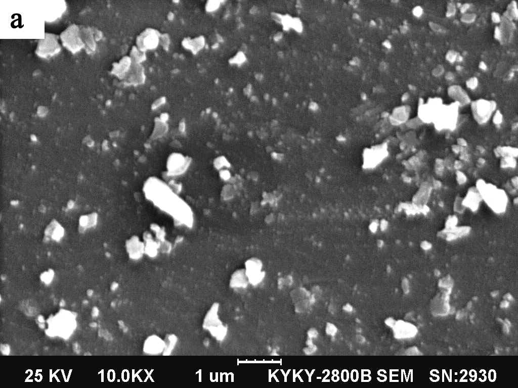
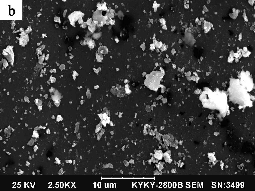
(a) x=0 ; (b) x=2
The morphologies of the Sr2-xCaxMgSi2O7:
Eu2+0.02,Dy3+0.04 (x=0,2) phosphors were observed by SEM and shown in Fig.2. It can be
seen that the initial particles are very small with the diameter below 100nm, and nearly
spherical in shape. It is because that the evolved gases ( N2, NH3,
CO2 ) can inhibit the particles agglomerating effectively.
Meanwhile, some big particles with irregular lamellar structure can be observed,
which may result from large surface energy of the initial small particles during the post
calcination process.
Crystallite size of powders was calculated from the peak broadening of
X-ray diffraction peak using the Scherrer formula:
D = 0.89 l/bcosq
Where D is the crystallite size in nm, the
radiation wavelength l is 0.154178nm for Cu Ka, b is
the corrected halfwidth, and q is the diffraction peak angle. The calculated crystallite size is
about 60nm and 50nm respectively for Sr2MgSi2O7 and Ca2MgSi2O7.
So, the crystallite size of as-synthesized powders is below 100nm.
|
|
Fig.3 Excitation spectrum of |
Fig.4 Emisssion spectrum of |
3.3 Excitation and emission spectrum of
the obtained phosphors
The excitation spectrum (monitored at 470nm) and the emission spectrum (excited by 400nm)
of as-synthesized phosphors are shown in Fig 3 and Fig.4. It can be seen that both the
emission and excitation spectra are broad-band continuous spectrum. The main excitation
peak is at about 400nm. From Fig.4, it can be seen that with the increasing of Ca(x=0,0.5,1,1.5,2)
doped in Sr2-xCaxMgSi2O7:Eu2+0.02,Dy3+0.04,
the main emission peak of the phosphors moves to the longer wave-length. When x=0,0.5,1,1.5,2,
the main peak value is located at 468nm, 483nm, 500nm, 512nm, 520nm, respectively. These
emission peaks results from the 4f65d→4f7(8S7/2)
transition of Eu2+ instead of the 4f7(6P7/2)→4f7(8S7/2) transition of Eu2+.
Because 5d electron is an external naked state without being shielded and the division of
its energy level is subject to strong influence of crystal field. So the 4f65d→4f7(8S7/2) transition of Eu2+
ion exhibits an emission peak with an obvious broad band. In addition, as previously
reported [8-9], different host structures and crystallographic distortions will
influence the crystal field environment of rare earth ions in the host structure, so the
emission peaks will vary greatly. In the akermanite structure
(Sr2-xCaxMgSi2O7), the alkaline
earth ions form chains along the c axis. With the increasing of Ca(x=0,0.5,1,1.5,2),
the length of the c axis decreases (rCa < rSr
), the orientation of an orbital will energetically become more favorable in this
sequence, which implies that the emission is expected to shift to lower energy(longer
wavelength)[5]. This is clearly observed in the Sr2-xCaxMgSi2O7:Eu2+0.02,Dy3+0.04
phosphors, for Sr2MgSi2O7:Eu,Dy(here x=0)
phosphor, which has the longest c-axis, the shortest wavelength emission can be
observed. For Ca2MgSi2O7:Eu,Dy( here x=2)
phosphor, which has the shortest c-axis, the longest wavelength emission can be
observed. That is to say, with the increasing of Ca(x=0,0.5,1,1.5,2) in Sr2-xCaxMgSi2O7:Eu2+0.02,Dy3+0.04,
the Eu2+ emission shifts to a long wavelength gradually. From these results, it
follows that the influence of the orientation of one d orbital on the emission
maximum is large. In addition, it can be seen from Fig.3 and Fig.4, the intensity of the
excitation and emission spectrums decrease with the increase of Ca doped in Sr2-xCaxMgSi2O7. A further investigation is needed to explain this phenomenon.
Under UV radiation at 254nm, no red-emitting of Eu3+ can be
observed, which indicates that it has been reduced to Eu2+ completely. The
special Dy3+ emission peak can not be observed in Fig.4, which shows that Dy3+
does not act as the luminescent centers in the Sr2-xCaxMgSi2O7
host crystal lattice, may be served as the traps of electrons or holes, or transfer the
light energy to Eu2+.
Fig.5 Decay curves of Sr2-xCaxMgSi2O7:
Eu2+0.02,Dy3+0.04 (x=0,0.5,1,1.5,2)
3.4 Long afterglow characteristic of
the obtained phosphors
The luminescent decay curves of Sr2-xCaxMgSi2O7:
Eu2+0.02,Dy3+0.04 (x=0,0.5,1,1.5,2) are
shown in Fig.5. The results show that the decay trend of the samples consists of three
parts. Initial rapid decay, middle transient decay and followed by very long slow decay.
The initial rapid decay is due to short survival time of electron in Eu2+, the
middle transient decay is due to the captures of Eu2+ ion by shallow trap
energy level center, and the long slow afterglow decay is caused by the electrons captured
in deep trap energy level resulted from Dy3+. It is obvious that the materials
have different long persistent properties. Both the initial intensity after excitation and
the afterglow intensity of the Sr2-xCaxMgSi2O7:
Eu2+0.02,Dy3+0.04 (x=0) phosphors were
higher than the other phosphors, it can be seen that with the increase of concentration of
Ca2+(x=0,0.5,1,1.5,2), the decay time and intensity are decreasing, Sr2-xCaxMgSi2O7:
Eu2+0.02,Dy3+0.04 (x=2) is the weakest
one, which indicating that the difference in host material probably has great effect on
the afterglow property of the obtained phosphors.
Based on the work of Jia et al[10], the possible
configuration coordinate model for Sr2-xCaxMgSi2O7:
Eu2+0.02,Dy3+0.04 long-lasting phosphorescence
is given in Fig.6.
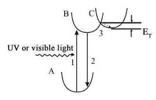
Fig.6 The configuration coordinate
model for the Sr2-xCaxMgSi2O7:
Eu2+0.02,Dy3+0.04 phosphor.
The possible long-lasting
phosphorescence mechanism of Sr2-xCaxMgSi2O7:
Eu2+0.02,Dy3+0.04 phosphor is as the
following: initially, visible light or UV light exposure excites the electrons transition
from the ground state (A) of the Eu2+ to an excited state (B)(transition 1) and
then one part of the excited electrons transit back to lower energy levels of Eu2+(transition
2) and the luminescence is observed. Meanwhile, some excited electrons can be stored in
the traps energy level(C) through the relaxation process(transition 3). The long-lasting
phosphorescence occurs when the electrons located in the trap energy level absorb energy
and are re-excited back to the excited state(B) and then cascade to the ground state. The
lasting time of phosphorescence depends on both the electrons number located in the trap
energy level(C) and the energy that the electrons absorbed should be larger than the trap
energy (ET) to ensure the electrons to be re-excited back to the excited
state(B). In this model, the trap may be created by the Dy3+ ions embedded in
the Sr2-xCaxMgSi2O7: Eu2+0.02,Dy3+0.04
matrix, or created by the oxygen vacancy formed in the reductive atmosphere. It has been
known that the trap levels located at a suitable depth dominating the thermal release rate
at room temperature have a pronounced effect on the afterglow[11]. As for these
Sr2-xCaxMgSi2O7: Eu2+0.02,Dy3+0.04(x=0,0.5,1,1.5,2)
phosphors, the duration time of Sr2MgSi2O7:Eu, Dy is much
greater than that of the others. The main reasons are ascribed to the more suitable depth
of Dy3+ traps and the good nature of the Eu2+ surroundings in the Sr2MgSi2O7
host.
4. CONCLUSIONS
Long afterglow luminescence materials Sr2-xCaxMgSi2O7:Eu2+0.02,Dy3+0.04
(x=0,0.5,1,1.5,2) was synthesized by gel-combustion method. This method
requires relative shorter reaction time and lower calcination temperature, it is safe,
instantaneous and energy saving. Both of the excitation spectrum and emission spectrum of
long afterglow luminescent materials Sr2-xCaxMgSi2O7:Eu2+0.02,Dy3+0.04(x=0,0.5,1,1.5,2)
are broad bands. The main excitation peak is at about 400nm. The main emission peak shifts
from 468nm to 483nm, 500nm, 512nm, 520nm with the increasing of Ca(x=0,0.5,1,1.5,2)
doped in host. As for these Sr2-xCaxMgSi2O7:
Eu2+0.02,Dy3+0.04(x=0,0.5,1,1.5,2)
phosphors, the dacay time and intensity decrease with the increase of concentration of Ca2+(x=0,0.5,1,1.5,2).
Among them, the duration time of Sr2MgSi2O7:Eu,Dy is much
greater than the others. The main reasons are ascribed to the more suitable depth of Dy3+
traps and the good nature of the Eu2+ surroundings in the Sr2MgSi2O7
host.
[1] Jia D, Meltzer R S, Yen W M et al. Appl. Phys. Lett, 2002, 80: 1535-1537.
[2] Huang L H, Zhang X, Liu X R. J. Alloys Comp, 2000, 305: 14-16.
[3] Takasaki H, Tanabe S, Hanada T. J. Ceram. Soc. Jpn, 1996, 104: 322-326.
[4] Yamamoto H, Matsuzawa T. J. Lumin, 1997, 73: 287-289.
[5] Poort S H M, Reijnhoudt H M, Blass G et al. J. Alloy Compd, 1996, 241: 75-81.
[6] Lin Y H, Tang Z L, Zhang Z T et al. J. Mater. Sci. Lett, 2001, 20: 1505-1506.
[7] Sabbagh Alvani A A, Moztarzadeh F, Sarabi A A. J.Lumin, 2005, 115: 147-150.
[8] Blasse G, Bril A. Philips Research Reports, 1968, 23: 201.
[9] Lin Y H, Zhang Z T, Tang Z L et al. Mater. Chem. Phys, 2001, 70: 156-159.
[10] Jia W Y, Yuan H B, Lu L Z et al. J. Lumin, 1998, 76-77: 424-428.
[11] Nakazawa E. J. Appl. Phys. Jpn, 1984, 23: L755-L757.
长余辉材料Sr2-xCaxMgSi2O7:Eu2+,Dy3+的凝胶-燃烧法合成和发光性质
(河北大学化学与环境科学学院,河北 保定071002)
摘要 本文采用凝胶-燃烧法合成了Sr2-xCaxMgSi2O7:Eu2+,Dy3+系列长余辉发光材料,用X射线粉末衍射(XRD)、扫描电镜(SEM)、荧光分光光度计等对合成产物进行了分析和表征. 结果表明:Sr2-xCaxMgSi2O7:Eu2+,Dy3+的晶体结构属四方晶系,一次颗粒细小,尺寸在100nm以下。激发和发射光谱均为宽带连续谱,最大激发峰位于400nm左右,随着Ca2+离子含量的增加,Sr2-xCaxMgSi2O7 (x=0,0.5,1,1.5,2)的发射峰位依次为468nm,483nm, 500nm, 512nm, 520nm,发光体颜色依次呈现出蓝,蓝绿,绿,黄绿,黄。余辉衰减曲线表明,发光体的余辉性能随着Ca2+离子含量的增加,而逐渐减弱,这可能与材料的微观结构不同有关。另外,与传统高温固相法相比,凝胶-燃烧法具有离子分散均匀,合成温度低,操作简单等优点。
关键词 Sr2-xCaxMgSi2O7:Eu2+,Dy3+,凝胶-燃烧法,长余辉,发光