http://www.chemistrymag.org/cji/2002/04b056pe.htm |
Aug.1,
2002 Vol.4 No.11 P.56 Copyright |
Abstract A novel electrochemical
reactor, three-phase three-dimensional electrode reactor (TTER) was designed and its
intrinsic performances of TTER were characterized with potential distribution and SEM
micrograph. The experimental results showed that it could effectively degrade aniline. Its
degradation efficiency mainly depended on applied voltage, Fe2+ concentration,
pH value and electrolysis time. It was found that the degrading of aniline in the presence
of Fe2+ was faster than in the absence of Fe2+. The result was
attributed to the Fe2+-mediated electro-Fenton process. The hydroxyl radical
generated by the process was confirmed by a spin-trapping ESR technology.
Keywords Electrochemical degradation, Three-dimensional electrode, Aniline,
Wastewater
1. INTRODUCTION
A variety of physical, chemical and biological techniques and their combinations have been
employed to remove organic pollutants. However, all existing wastewater treatment
processes have their inherent limitations in applicability, effectiveness and cost[1].
These limitations have spurred an effort to develop new and effective technologies for
detoxification and removal of undesirable organic substance [2].
Recently, interest in environmental electrochemistry, an emerging
technology, has been increased and possible application for the treatment of effluents
from industrial or municipal plants can be envisaged[2, 3] in view of various
advantages like easy control, versatility, amenability to automation and environmental
compatibility[3]. In particular, the electrochemical technologies based on
three-dimensional electrodes, such as packed bed or fluidized bed electrodes, for
wastewater treatment have attracted much more attention [2-5] because the
electrodes are characterized by large specific surface areas and high performance in
comparison to conventional two-dimensional electrode [2, 5]. However, most of
researches about the three-dimensional electrode are mainly focused on organic
electrosynthesis [6, 7] and removal of metal ions from wastewater streams[8].
Up to now their application to eliminating organic pollutants from wastewater is still
rarely reported. Our attention has been paid to develop a novel electrochemical reactor,
three-phase three-dimensional electrode reactor (TTER), adaptable to degradating organic
pollutants[9] .
2. EXPERIMENTAL
2.1. Material
Reagent grade chemicals and deionized water were used throughout the work. Aniline solutions were prepared by using deionized water to a concentration of 400 ppm and adjusted to a desirable pH value with H2SO4 and its concentration was analyzed by UV spectrophotometer. The granulated activated carbon (GAC) used as the packed bed particulate electrode has a surface area of 870.0 m2/g , an average particle size of 3.5¡Á5.1 mm and ash content of 8.1%. Both the main electrodes (feeder electrodes) were made of graphite plate. The reactor and electrodes were washed thoroughly with deionized water prior to each experiment.
2.2 Apparatus
Optical absorption scan spectra of aniline were recorded with an UV-PC2501 spectrophotometer (Hitachi, Japan). pH value was determined by PHS-3C (Shanghai Rex Instrument Factory). SEM images were obtained on a JSM-6330F-mode Field Emission Scanning Electron Microscope (JEOL, Japan). Cyclic voltammetry experiments were carried out using CHI650A (Shanghai, China) potentiostat with Silicon-Pt electrode (South Korea) in aqueous solution.
2.3 Electrochemical Reactor
TTER used is a batch cuboid undivided three-phase three-dimensional electrode reactor as shown in Fig. 1. The reactor mainly consists of four parts, support, anode and cathode, GAC packed bed and compressed air. The support was made of plastics with a size of (14¡Á12¡Á6) cm3. The anode and cathode (main electrodes) were made of graphite electrodes (14 cm¡Á6 cm¡Á2 cm) situated 8 cm apart from each other. The 500 g GAC with a bed height of 5 cm was packed between the two main electrodes, forming a cubic packed-bed three-dimensional electrode i.e., working electrode. The compressed air was sparged into the particle electrodes by a micopore plate from the bottom of the reactor. The sparging of the compressed air into the reactor will cause an increase in the height of the packed-bed, such as, for airflow of 0.1 l min-1, the increase by height about 1 cm. The electric power was supplied with regulated DC power supply.
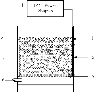 |
Fig.1
Schematic diagram of three-phase three-dimensional electrode reactor |
2.4 Experimental Procedure
Prior to electrolysis, the main electrodes were washed with
dilute sulphuric solution and then rinsed with amount of deionized water. All GAC
particles were dipped in the solution for adsorption to reach saturation in order to
eliminate the contribution of adsorption to the removal in the process of electrolysis. A
250.0-ml solution of 400 ppm aniline was fed into the reactor. The reactor was timed
starting when the DC power and compressed-air supply were switched on. General treatment
condition are pH 5.8, cell voltage 10.0 V, airflow 0.1 l min-1and treatment
time 30.0 min unless otherwise stated. The resulting solution was analyzed using UV
absorption and cyclic voltammetry techniques.
3. RESULTS AND DISCUSSION
3.1 Potential Distribution of Particle Electrodes and Solution in TTER
The unifying feature for three-dimensional electrodes is that the cell chamber is filled
or partly filled with required working electrode materials depending on the aim of
research. In aqueous medium, activated carbon has considerable electrochemical activity[11],
in addition to its strong adsorption efficiency. Hence it has been receiving increased
attention recently for its utilization as an electrode material[12]. In this
present study, the GAC was employed as the packed material, also named particle
electrodes. For any packed-type electrochemical reactor, potential distribution is a
significant parameter charactering the reactor. As a result, the potential distribution on
the particles and solution were simultaneously determined using a Pt wire as probe. As
shown in Fig. 2, the potential increase slowly with increasing the distance from the main
cathode before 4 cm, then increase rapidly. It was also observed that potential in
solution was apparently lower than that on the particle electrode at the same position and
the greater their difference, the closer to anode the position. The fact implies these
particle electrodes were polarized. Due to that these particle electrodes have greater
member resistance, each GAC can be regarded to be independent small electrode with itself
anode and cathode. As a sequence, TTER have a considerable total area of electrode. It is
reasonably expected that organic pollutant can be efficiently degraded in TTER via direct
or indirect oxidation.
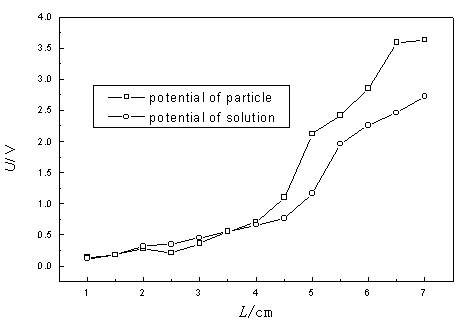
Fig.2 Potential distribution in TTER
3.2 SEM micrograph of the Particle Electrode
Fig.3 depicts the SEM micrographs of the GACs after used as particle electrode at an
applied cell voltage of 10 V (a), after used in the chemical adsorption (b) and the
original GACs (c), respectively. It can be observed from these micrographs that the
aperture of the materials after the chemical adsorption is smaller than that of original
materials while the aperture of the packed electrode after electrolysis is bigger than
that of the original materials. The former is probably ascribed to the reason that the
apertures of the materials are partly filled by the adsorbed material, leading to a more
compact surface. The reason of the latter remains unclear, however, the difference of the
SEM micrographs can be considered as an evidence that the processes which occurs on
surface of the GAC in TTER during the electrolysis are the related electrochemical
reactions, anodic oxidation or/and cathodic electrogenerated H2O2,
not simple adsorption.
3.3 Evidence for Generation of Hydroxyl Radicals
The three-phase three-dimensional electrode reactor used in this study is a kind of undivided electrochemical reactor based on the combination of GAC packed-bed electrode and air-fed gas¨Cdiffusion electrodes, differing from the reported three-dimensional electrode (only solid and liquid phases)[9,10]. The compressed air was uniformly sparged into the cell by a micropore plate. The sparged air serves two purposes. One is to agitate in order to speed mass transfer, also to clean and activate, in situ, the surface of particle electrodes. Another is to supply the essential oxygen for electrochemical reactions because some authors have reported that the oxygen can be changed into stronger oxidizing agent H2O2 on activated carbon electrode by the following two-electron reduction of oxygen[13]:
O2 + 2H+ + 2e ¡ú H2O2 (1)
The TTER can simultaneously make use of anodic oxidation and cathodic electrogenerated H2O2 to degrade organic pollutants. If Fe2+was added to TTER, expectedly, the hydroxyl radicals, a stronger oxidant than H2O2, can be generated via Fenton reaction, are beneficial to the degradation of organic pollutants.
 (a)
(a) |
 (b) (b) |
 (c) (c) |
Fig.3 SEM
micrographs of samples a: The particle electrode used in electrolysis; b: The particles used in the chemical adsorption; c: The original material |
However, the hydroxyl radical cannot be directly determined so far due to its short
lifespan, less than 10-4 s. In our experiment, an indirect method, spin trapping,[14] was
used to confirm the existence of hydroxyl radical in the three-phase three-dimensional
electrode reactor and DMPO was selected as trap reagent of hydroxyl radical. The trapping
reaction is showed as follows:

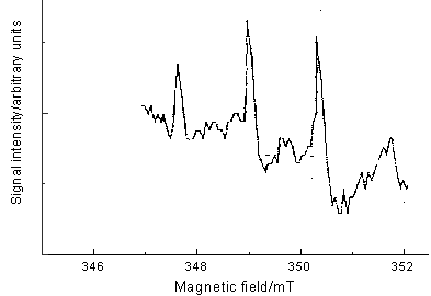
Fig.4 ESR spectrum of DMPO-OH
The DMPO-.OH radical is more stable and longer life-span
than hydroxyl radical and can be determined by ESR technology. The ESR spectrum of the
solution after 10.0-min reaction in the electrochemical reactor is given in Fig. 4. An apparent quadruple pattern of DMPO-.OH adducts with characteristic
1:2:2:1 in the figure was observed, suggesting the existence of hydroxyl radical in the
used reactor.
Although the life-span of
hydroxyl radical is less than 10-4s, its power of
oxidation is rather strong (2.8 V vs. SCE), much higher than the oxidation-reduction
potential of aniline (about 0.6-0.8 V vs. SCE). As a result, in the presence of Fe2+
ions, aniline was more easily oxidized in TTER compare with the case in absence of Fe2+
ions.
3.3 Degradation efficiency of Aniline in
TTER
The experimental results were assessed mainly with degradation efficiency (%), i. e., the
ratio of the absorbency reduction after treatment to the initial absorbency of the aniline
solution. It was found that TTER could degrade aniline in aqueous solution, however, the
degradation efficiency was considerably dependent on applied cell voltage, Fe2+
concentration, pH value and electrolysis time.
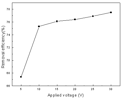
Fig.5 Effect of applied voltage on removal efficiency (operating
conditions: 10 V applied cell voltage, 0.1 L/min-1 airflow and 30.0 min
treatment time)
Fig. 5 presents the
dependence of applied voltage on removal of aniline for an electrolysis time of 30
minutes. It can be seen from the figure that the degradation of aniline is increased with
increasing voltage, but the enhancement extent is different in various voltage ranges.
When the applied voltage is lower than 10.0 V, the degradation increased rapidly with
increasing in the cell voltage; when the applied voltage is higher than 10.0 V, there is
no apparent increase in removal efficiency of aniline. The enhancement effect of applied
cell voltage can be reasonably attributed to the increase in the driving force of the
electrode reaction since potential is the major driving force in electrochemical reactor [11]
while the phenomenon that enhancement effect is not proportional to the increase in cell
voltage is resulted by the occurrence of some parasitical side reactions as the applied
voltage is more than certain voltage, such as decomposition of water:
2H2O ¡ú 4H++ O2 +4e
(3)
Fig. 6 presents the dependence of the degradation efficiency on Fe2+
ion concentration. As expected, Fe2+ can apparently increase the aniline
removal efficiency of the TTER and moreover it is still observed that the removal
efficiency still increase with increasing in the concentration of Fe2+ in the
experimental range. In other words, the increase could be regarded as another evidence for
the occurrence of Fenton reaction in the reactor. As a sequence, the following experiments
were carried in the presence of Fe2+ ions.
The effect of pH value on the removal efficiency of aniline with an electrolysis time of 30 min is shown in Fig. 7. The initial pH values of the supporting electrolyte were set at 2.1, 3.0, 4.0, 5.8 and 7.6 in order to determine the influence of pH on the indirect oxidation reactions. As it can be seen in the figure that the pH value of the reaction medium is one of the important factors affecting removal efficiency of aniline and the degradation of aniline rapidly decrease with the increase in pH value. Although aniline exists in a protonated form that is unfavorable to anodic oxidation of aniline, the reaction of the electrogenerated hydrogen peroxide prefers to the lower pH value, as shown in the reaction (2). The result may indicate that the H2O2 generation involving H+ is a rate-determining step in the process of aniline degradation, as suggested by Brillas et al.[15].
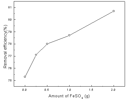
Fig. 6 Effect of Fe2+ concentration on the degradation efficiency of aniline (operating conditions: 10 V applied cell voltage, 0.1 L/min airflowand 30.0 min treatment time).
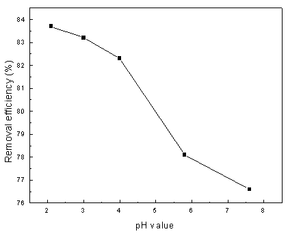
Fig. 7 Influence of H+ on removal efficiency (operating
conditions: 10 V applied cell voltage, 0.1 L/min
The dependence of the removal efficiency of aniline on electrolysis time at the conditions of 10 V applied cell voltage, 0.1 l min-1 and 0.25 g FeSO4 is presented in Fig. 8. They show that the removal efficiency increases rapidly during the first 30-min and about 81.7% aniline is removed within 30 min. However, the increase of removal efficiency get slow after 30.0 min and the tardiness of aniline removal efficiency may be due to competition with intermediate oxidation.
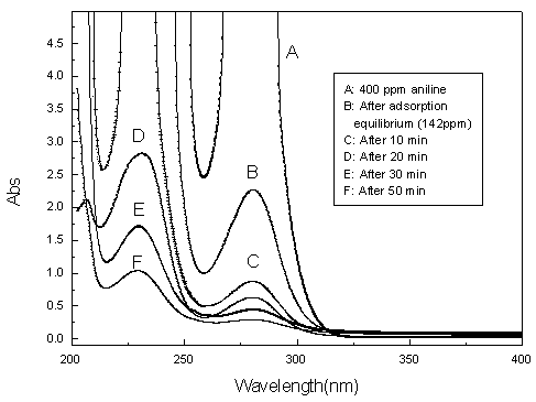
Fig.8 UV spectra of aniline at various reaction intervals
Aniline and the treated
solution was also studied using cyclic voltammetry technology and the cyclic voltammograms
are presented in Fig. 9. The anodic and cathodic peaks of anline was observed to be
consistent with that reported by Bacon et al.[16]. However, no apparent anodic
and cathodic peak (curve b and c) was observed for the treated solution, suggesting that
most of aniline was degraded, however, from the absorbency of rim peak of Fig.8 (200 nm),
it can be seen that considerable intermediates still remain in the treated solution. It
can be expected that these intermediates will be also further degraded with prolonging
treatment time.
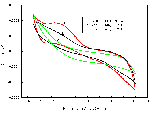
Fig. 9 Cyclic voltammograms of aniline and treated solution (scans region
¨C 0.6 ~ 1.2 V vs SCE)
4. CONCLUSION
A novel electrochemical reactor, TTER, has been
designed for degrading organic pollutants and used for investigating the degradation of
aniline. It is found that this
technology removes aniline effectively. The
effectiveness can be contributed to the anodic oxidation and indirect oxidation of
cathodic electrogenerated H2O2 and hydroxyl radical in the novel
reactor. The experimental results show that the efficiency of degradation organics depends
on the applied cell voltage, Fe2+ concentration, pH and electrolysis time. The
three factors of Fe2+ concentration, electrolysis time and the applied cell
voltage had a positive effect on the removal efficiency. It is expected that the further
investigations will lead to the emerging of a new technology to treat actual organic
wastewater treatment.
REFERENCES
[1] Ray A K, Catal. Today, 1998, 44: 357.
[2] Simonsson D.
Chem. Soc. Rev. 1997, 26 (3): 181.
[3]
Rajeshwar K, Ibanez J G, Swain, G M J. Appl. Electrochem, 1994, 24: 1077.
[5] Bockris J O M, Kim J. J. Appl. Electrochem., 1997, 27: 890.
[6] Scott L L, Winnick J, Kohl P A et al. J. Electrochem. Soc., 1998, 145: 4062.
[7] Szanto D, Trinidad P, Walsh F. J. Appl. Electrochem., 1998, 28: 251.
[8] Ragnini C A R, Di I R A, Bizzo W et al. Water Res., 2000, 34: 3269.
[9] Xiong Y, Strunk P J, Xia H et al. Water Res., 2001, 35: 4226.
[10] Gheewala S H, Annachhatre A P. Wat. Sci. Tech., 1997, 36 (10): 53.
[11] Kastening B, Boinowitz T, Heins M. J. Appl. Electrochem., 1997, 27: 147.
[12] Canizares P, Dominguez J A, Rodrigo M A. Ind. Eng. Chem. Res., 1999, 38: 3779.
[13] Alverez-Gallbergos A, Pletcher D. Electrochimica Acta, 1999, 44: 2483.
[14] Morelli R, Bellobone I R, Chiodaroli C M et al. J. Photochem. Photobio. A: Chem. 1998, 112: 271.
[15] Brillas E, Mur E, Casado J J. J. Electrochem. Soc., 1996, 143: L49.
[16] Bacon J, Adams R N. J. Am. Chem. Soc., 1968, 90: 6596.¡¡
¡¡