http://www.chemistrymag.org/cji/2000/026028pe.htm |
Jun.14, 2000 Vol.2 No.6 P.28 Copyright |
An Analysis of Interfacial Surface Areas of PAFC Air Electrodes
Wei Zidong,
Tan Jun, Zhang Shengtao, Chen Changguo, Huang Wenzhang , Wang Quntao, Tang Zhiyuan# ,
Guo Hetong#
(Department of Applied Chemistry, Chongqing University, Chongqing , 400044; #Department
of Applied Chemistry, Tianjin University, Tianjin , 300072 , China)
Received January 16, 2000; Supported by the National Natural Science Foundation of China. (Grant No.29976047)
Abstract A model of the air electrode
used in PAFC was developed. The model can characterize the behavior of a PAFC air
electrode at a wide range of current densities and at any operation gas pressure. The two
parameters AB and AI were introduced into the model, The parameter AB, mainly reflecting
the effects of the interfacial surface area between gas and liquid phases on the air
electrode performance, was proved to has a different linear relationship with the current
density at a different gas pressure. With the increase of operation pressure, AB gets to
become less dependent of current density I. The parameter AI, mainly reflecting the
effects of the interfacial surface area between liquid and solid phases on the air
electrode performance, was proved to keep nearly unchanging at any current density and gas
pressure. The study also showed that the reaction rate was not uniform across the reaction
layer.
Keywords air electrode, PAFC, mathematical model.
The phosphoric acid fuel cell (PAFC) is
capable of providing a clean, efficient, and high-powered source of electric energy. Its
relative mature in technique has made PAFC an attractive commercial prospect. PAFC has
undergone many advances in past years due to improved electrocatalysts and electrode
structure, and also due to optimization of operating conditions and cell design. For
example, improved electrocatalysts has led to the dramatic reduction of platinum loading
from early 10 mg/cm2 to current 0.5 mg/cm2. The PAFC operating under
a high pressure and a high temperature has displayed a higher power output. After several
decades of effort PAFC is approaching commercialization. The founding of an 11 MW PAFC
plant at Goi. (Japan) in 1991 for a prototype demonstrator marked the beginning of this
kind of fuel cells commercialization [1,2]. However, for its complete
commercialization, further capital cost reduction is certainly required. The performance
of PAFC also needs to be improved.
Mathematical modeling of fuel cells can supply a convenient approach to
assess the influence of electrode structure parameters and operating conditions on the
various types of polarization, which consequently affect the performance of a fuel cell.
The 'uniform electrolyte film' concept, a widely accepted physical model of porous
electrodes was first proposed by Cutlip [3]. Afterwards, Tian proposed a
'uneven-uniform electrolyte film' model [4]. Cha and his coworkers also
established a formula reflecting the relationship between the current density and
overpotential [5]. Recently, Vidts and White tried to give a general governing
mathematical model for any porous electrode in an imaginary binary solution based on
so-called 'volume-averaging technique'[6]. Almost all models established to
date took the surface areas between two phases i.e., gas/liquid and liquid/solid as two
constants. However, Zhou's experiments [7] showed that the electrolyte films in
Teflon-bonded porous electrodes got thinning with the increase of overpotential. The
experiments in the authors' laboratory also confirmed Zhou's conclusion. This phenomenon
indicates that the conventional view on the interfacial surface area between two phases is
questionable .The present model is distinct from the previous ones in that the interfacial
surface area between gas and liquid is no longer taken as a constant for different current
densities. The relationship between the parameter AB and current densities is formulated
in the present paper. The reaction rate throughout the reaction layer of PAFC air
electrode is analyzed using the proposed model. The conclusions from the numerical
analysis of the model are novel and worth deep consideration.
1. Mathematical Model for PAFC Cathode
An improved model based on Cutlip's[3] was
presented by the authors previously [8,9] .The parameters of the air electrode
structure and operation conditions on which Cutlip's model was established deviated from
the actual state of the current PAFC. For instance, the pore size in the Teflon-bonded
catalyst layer is much larger than that adopted by Cutlip. Even though the pore size of
catalyst layer has a wide distribution, the micro-pores in the catalyst layer are thought
to be filled by electrolyte because they have much stronger capillary force than
macro-pores, which are tunnel of gas diffusion. The size of macro-pores is so large that
the Knudsen diffusion can be ignored [10]. Besides Cutlip's model didn't
involve the operation condition in which the gas pressure was over one atmosphere.
Therefore, Cutlip's model did not correctly demonstrate the real situation of today's
PAFC. The latest developments in oxygen reduction research and the structure parameters of
PAFC in operation were taken into accounts in construction of the present model.
The main assumptions on which the
model was based are as follows:
(a) Kundsen diffusion of multi-component molecular diffusion is not
considered either in the gas diffusion layer or in the reaction layer.
(b) The drop of multi-component pressure within gas diffusion layer is
negligible according to the calculation of Ref [8].
(c) The gas-diffusion layer is described by a homogeneous continuum
consisting of gaseous-filled layer and solid electrode framework. Similarly the reaction
layer can be described by superimposing the gaseous-filled and liquid-filled pores with
solid electrode framework.
(d) The potential distribution within the air electrode is not included
into the model because it is almost unchangeable throughout the reaction layer [3].
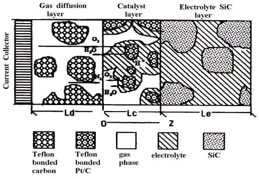
A schematic of the PAFC cathode is shown in Fig .1, which also displays
the process occurring in the cathode.

Fig.1 Schematic of air electrode of PAFC
A one-dimensional mathematical model of the reaction layer of PAFC cathode can be written in the following differential group [8,9].
dP1 /dZ = ( RTN1 / P ) ( -2 P1 / D12 - P2 / D12 P3 / D13 ) (1)
dP2 /dZ = ( RTN1 / P ) ( 2 P1 / D12 - P2 / D12 + 2 P3 / D23 ) (2)
dP3 /dZ = ( RTN1 / P ) ( 1 / D13 2 / D23 ) (3)
dN1/dZ = - P1 / ( 4F / ( a l i0 exp ( 2.3 (Er E ) /Ts )) + d/ag Dl C10 ) (4)
The boundary conditions for the above the above each equation are
Pi = Pi ( 0 ) (i = 1 , 2 , 3) (5)
Ni (0 ) =0 (6)
Where
Dij=Dijr ( T / T r ) 1.75 ( P r / P) ecg / tc [10] (8)
2. SOLUTION OF THE MODEL
The critical structure parameters which determine the performance of porous electrodes are
the interfacial surface area between gas and liquid phase, i.e. ag , and the
area between liquid and solid phrase , i.e. al . They were thought unchangeable
previously. For example , Kimble and White took al times exchange currents ( i0
) as 0.60 A cm-3 , and ag divided by
diffusion layer thickness of dissolved oxygen in electrolyte film (d) as 5.108
cm-2[11]. Actually the above-mentioned parameters cannot be independently
determined from experiments and therefore must be obtained from the other experimental
data. The curve fitting or more advanced optimization method is a common approach to solve
the uncertain parameters. In order to minimize the number of fitted parameters and avoid
using questionable values of some parameters, several uncertain parameters are merged into
the following two parameters:
AB = a g D l C10 / d
(10)
AI = a l i 0
(11)
Then the equation (4) has a new form (12)
dN1/dZ = - P1 / ( 4F / ( AI exp ( 2.3 (Er E ) /Ts
)) + 1 / AB )
(12)
Finally, the four governing equations for the reaction layer of PAFC cathode are Eq. (1),
(2), (3) and (12).

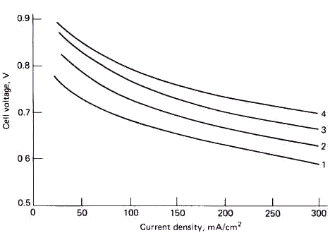
Fig.2 Phosphoric acid fuel cell-performance for a range of pressures ( at
start of test )
(1)Atmospheric pressure, 190°C, 0.5mg/cm2
Pt on carbon (2) 3.105Pa,
190°C, 0.5mg/cm2 Pt on carbon
(3) 6.105Pa, 210°C, 0.5mg/cm2
Pt on carbon (4) 8.105Pa,
220°C, 0.5mg/cm2 Pt on carbon
A computer program TMSTB purchased from the Computer Center of Academia
Sinica was used to solve the differential equations group. An accelerated method called
Simplex [12] was used to search the optimum values of parameter AB and AI. This optimum
method can automatically expand and contract the searching step then greatly accelerates
the searching rate of the Simplex. The objective function G is defined as
![]() (13)
(13)
Where, Ik and Ik, model are the current densities from the
experiments as shown in Fig.2 and from the calculation of the model respectively. The
current density Ik , model is calculated from N1, i.e. ,
Ik , model =N1 (0) / 4F
(14)
The magnitude of G also reflects the deviation of the model from the experiment .The less
of G in value, the closer the model to experiments.
The subroutine program for optimization of AB and AI is named
SUBROUTINE OPT. The block diagram of computing is shown in Fig .3
Fig .3 The block figure of the model calculating program
3. RESULTS AND DISCUSSION
The operating conditions and the cathode potential E were substituted into the
mathematical model to calculate the current densities Ik , model .
If AB and AI were taken as a single value respectively in all range of
current densities to meet the demand of Eq. (13), there was a great deviation between Ik
, model and Ik although the results predicted by the model followed the
tendency of experiments by and large as shown in Table 1.
Table 1 Comparison between the experimental Ik
and the model predicted Ik , model as AB and AI keep constant in all
range of current densities
| Ik
( mA·cm-2 ) |
Ik , model ( mA·cm-2 ) |
|||
Curve 1 |
Curve 2 |
Curve 3 |
Curve 4 |
|
27 |
24 |
25 |
25 |
23 |
35 |
30 |
28 |
29 |
30 |
38 |
33 |
32 |
33 |
34 |
50 |
49 |
48 |
48 |
48 |
55 |
57 |
61 |
60 |
59 |
74 |
80 |
88 |
84 |
80 |
112 |
136 |
140 |
149 |
137 |
188 |
201 |
214 |
217 |
215 |
300 |
269 |
258 |
253 |
261 |
AB×104 ( mol.cm-3.s-1 ) |
1.25 |
1.36 |
1.69 |
1.74 |
AI×102 ( A.cm-3) |
3.66 |
1.08 |
0.52 |
0.43 |
G×102 |
7.16 |
16.56 |
15.21 |
9.74 |
Based on the fact that the electrode behavior is always
highly dependent on the current density, the scale of current densities was divided into
two sections to fit the Eq. (13), one from zero to 100 mA.cm-2
and the other from 100 mA.cm-2
to 300 mA.cm-2.
The parameters AB and AI were respectively optimized at the two sections. The difference
between Ik , model and Ik was markedly reduced. Meanwhile, the value
of AB was quite different at the two sections. Based on this fact, parameters AB and AI
were optimized point by point along experiment E-I curve. It was surprised to learn that
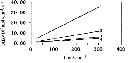
the parameter AB was completely linear with the current density at each operating gas
pressure. While parameter AI was nearly free of the current density. In fact, parameter AI
oscillated only in the range of (4.2 ± 5%) .10 -2 (A.cm-3).
As parameters AB and AI were required only to satisfy the minimum of G
for one point, i.e.. m=1 in Eq. (13) . The Eq. (13) can be easily satisfied with a very
low value of G. Mostly, G is less than 1.10
-14 . It means that the current density from experiments is nearly equal to that
from the model. Consequently, the foregoing assumption resulting in this result is
probably reasonable.
It had been found that parameter AB and current density I had the following relationship:
AB = l + w I
(15)
The relationships between AB and I are shown in Fig.4.

Fig4. The relation of AB and AI at a range of the pressure (1) 1.105Pa (2) 3.105Pa (3) 6.105Pa (4) 8.105Pa
From the definition of parameter AB, i.e. AB = ag DC10
/d , the variation of AB with the current density
actually reveals the relationship between ag /d
and the current density. The phenomenon that the parameter AB increases with the current
density means an increase of the interfacial surface area between gas and liquid phase ( ag
) and/or a decrease of the thickness of the electrolyte film (d)
. This novel conclusion had been already contested by Zhou and Poorten[7] . In light of Kimble and White's research[11], the three-phase electrode should contain a large
number of gas-liquid sites. It can be easily drawn from Fig.4 that the high current
density is benefit for a high-energy output of a porous electrode. The data related to gas
pressure is not sufficient enough for deducing a certain relationship between parameters
AB and the gas pressure. However, the decreasing tendency of AB at a given current density
with the gas pressure can also be disclosed in Fig.4. This phenomenon suggests that the
high gas pressure will reduce the interfacial surface area between gas and liquid phase,
although it can increase the reactant gas concentration in catalyst surface. The gas
pressure has a contrary effect on the electrode performance. The extra-high pressure is
not always positive for achieving a high-energy output. It can also get a conclusion from
Fig.4 that AB gets to become less dependent of current densities with the increase of
operation pressure. This is coincident with the conventional view, i.e., the interfacial
surface area between gas and liquid is a parameter free of current densities.

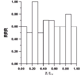
Fig5. The relative reaction rate on the catalystlayer at the current density of
100mA.cm-2 at the pressure of 3.105Pa
The flux distribution of oxygen across the catalyst layer can be converted into an index indicating the electrochemical reaction rate across the dimensionless reaction layer. The reduction of N1 in magnitude from Zi to Zi + DZ, i.e. DN1 (Zi) equals the electrochemical reaction rate in the thickness of DZ. The relative reaction rate (RRR) i.e., the ratio of DN1 (Zi) to the Max {DN1 (Zi)} vs. (Z/Lc) are demonstrated in Fig .5, from which it can be observed that the reaction rate is not uniform throughout the reaction layer. The results also display that the two maximum points appear at Z / L c = 0.3 and Z / L c = 0.9 respectively.
3. CONCLUSION
A mathematical model of an air electrode used in PAFC has been developed. The parameters
AB and AI characterizing the three-phase electrode are introduced into the model. When AB
and AI are taken as constants from zero to 300 mA.cm -2 of current
density, the relative error of the current density predicted by the model will be up to 17
% relative to that by the experiments. When parameters AB and AI are fitted below and
above 100 mA.cm -2 respectively, this error will drop to less than 5
%. This means that the interfacial area between gas and liquid phases is highly relative
to current densities. Furthermore, the AB and AI are fitted at each single current
density. The above-mentioned error is nearly negligible. It is also found that parameter
AB is proportional to the current densities at a given operation pressure, but it gets to
become less dependent on current densities with the increase of operation pressure.
Parameter AI just oscillates in a very narrow range for all current densities. At a lower
operation pressure, the increase of parameter AB with the current density indicates that
the high current density leads to more efficient utilization of air electrodes. At a
higher operation pressure, however, the increase of current densities dose not play the
same role as it dose at a lower operation pressure
LIST OF SYMBOLS
ag
interfacial surface area between gas and liquid phase , cm2.cm-3
al interfacial surface area between liquid
and solid phase , cm2.cm-3
AB parameter defined by Eq .(10) , mol.cm-3. s-1
AI parameter defined by Eq .(11) , A. cm-3
C10 solubility of oxygen in the electrolyte at 1.103×10⁵ Pa ,mol. m-3. Pa-1
Dl diffusion coefficient of oxygen dissolved in the
electrolyte , m2. s -1
Dij effective gas diffusion coefficient for component i and j
at the given pressure , m2. s -1
Dijr effective gas diffusion coefficient for component i
and j at the reference state, m2. s -1
E electrode potential , V
E0 open circuit potential for
oxygen electrode , V
F faraday's constant , 96,487 C. mol-1
G function defined by Eq.(13)
I current density , A. cm -2
Ik current density from experiments , A.cm
-2
Ik,model current density calculated from the model , A.cm
-2
i0 exchange current density , A.cm-2
N1 flux of oxygen , mol.cm -2.s -1
P total pressure in the gas stream and porous backing , Pa
Pi partial pressure of component i , Pa
r relevant coefficient
R gas constant , 8,314 J. mol -1. K -1
RRR relative reaction rate, i.e., the ratio of DN1
(Zi) to the Max{DN1 (Zi) }
T temperature , K
Tr reference temperature , K
Ts tafel slope , V/decade
Z spatial coordinate , cm
d thickness of electrolyte film , cm
e porosity
t tortuosity
l parameter in Eq . (15) , mol.cm
-3. s -1
w parameter in Eq . (15) , cm -1
Superscripts
g gas phase
l liquid phase
r reference
Subscripts
c catalyst layer
d gas diffusion layer
i species i , i = 1 ,2 ,3 corresponding to O2 , H2O
(g) , N2 respectively
REFERENCES
[1] Yi B L. Power Technology (Dianyuan Jishu), 1998, 22: 216.
[2] Appleby A J. J. Power Sources, 1996, 69: 153.
[3] Yang S C, Cutlip M B, Stonehart P. Electrochim. Acta, 1990, 35: 869.
[4] Tian Z W. Chinese Science (Zhongguo Kexue), 1981, 44 (2): 581.
[5] Zha Q X. Introduction of electrodes (Dianji Guocheng Donglixue Daolun) , Beijing:
Chinese Science Press , 1987: 370.
[6] Vidts P, White R E. J. Electrochem. Soc., 1997, 144: 1343.
[7] Zhou D B, Poorten H V. Electrochim. Acta , 1995, 40: 1819.
[8] Wei Z D, Guo H T, Tang Z Y. Acta Physico-Chimica Sinica (Wuli Huaxue Xuebao) , 1996,
12 : 1022.
[9] Wei Z D, Guo H T, Tang Z Y. Chem. J.Chin. Univ. (Gaodengxuexiao Huaxue Xuebao) , 1996,
17: 1760.
[10] Thomas K S, Robert L P, Charles R W. Mass Transfer, New York: McGraw-Hill, 1975, 18.
[11] Kimble M C, White R E. J. Electrochem. Soc., 1992, 139: 478.
[12] Zhou Z M, Tan S Y. Computer application in chemistry and chemiscal engineering
(Jisuanji Zai Huaxue Huagong De Yingyong) , Chongqing: CQU Press, 1996, 188.