http://www.chemistrymag.org/cji/2005/072018pe.htm |
Feb.10, 2005 Vol.7 No.2 P.18 Copyright |
Sun Mengtao, Song Peng, Lee Chunxia, Wang Weili, Lee Yongqing, Ma Fengcai
(Department of Physics, Liaoning University, Shenyang, 110036, China)
Received Nov. 9, 2004; Supported by the National Natural Science Foundation of China (Grant No. 10374040).
Abstract Collisonal quantum interference (CQI) was observed in the intramolecular rotational energy transfer in the experiment of the static cell, and the integral interference angles were measured. To observe more precise information, the experiment in the molecular beam should be taken, from which the relationship between the differential interference angle and the scattering angle can be obtained. In this paper, the theoretical model of CQI is described in an atom-diatom system in the condition of the molecular beam, based on the first-Born approximation of time dependent perturbation theory, taking into account the anisotropic Lennard-Jones interaction potentials. The method of observing and measuring correctly the differential interference angle is presented. The changing tendencies of the differential interference angle with scattering angle, including the impact parameter, velocity, and collision partner are discussed. 1 INTRODUCTION
Quantum interference (QI) on chemical dynamics is one of main subjects experimentally and theoretically. Experimentally, the QI was studied on rotational energy transfer [1-6], Theoretically, the QI was also studied [7-15] and reviewed [16] on rotational energy transfer. In the open-shell P-states diatomic molecules electronic states, the collisional quantum interference on rotational energy transfer was observed experimentally[1], which results from the
where c and d are the mixing coefficients, and
2.1 Hamiltonian
For the atom-diatom system, the Hamiltonian is given as [11],
where
where S and T represent the singlet and triplet states respectively. The electrostatic interaction potential between the atom and the two electronic states of the diatom in the space frame [27] is,
where
where
where
and where the Hamiltonian of
In this letter, without considering the translational, electronic and vibrational energy transfer, so
and for the
where
2.2 Perturbations between singlet and triplet states
The unperturbed wave functions are
 (12)
(12)where the singlet [7] and triplet[22] wave functions are
The zeroth order unperturbed energies are defined as
The perturbed wave functions [29, 11] are
 (16)
(16)Eq.(15) shows that the mutual perturbing states are repulsive each other. The energy level shifts
where
In the later derivation, according to Eq. (15), we set that the mixing coefficients
and
2.3 The transition matrix element and probability
According to the first order Born approximation of time dependent perturbation theory, the transition matrix element is,
where only electrostatic interaction is involved with no magnetic coupling present [3-5, 11], i.e., a transition between the two states is prohibited,
 (22)
(22)and the transitional matrix of the triplet state is [22],
 (23)
(23)and the coefficients
Introduce Eq. (21) into Eq. (24), consider the orthogonal relationship of the three J symbol, one can obtain,
where
 (26)
(26)Similar to Eq.(1), Eq. (25) also can be written as the form,
with the differential interference angle
 (28)
(28)the relationship between the differential interference angle and the integral interference angle are discussed in Refs [7-15].
3 DISCUSSION
3.1 Obtaining the anisotropic parameter,
Considering the anisotropic Lennard-Jones interaction potentials, Eq. (5) can be written as,
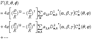 (29)
(29)In Eq. (29),
 (30)
(30)where
and
 (32)
(32)To simplify the discussion, the rigid sphere interaction potential is considered, and the scattering angle for the rigid sphere potential [23] is
So in integrating over the impact parameter, for
The integration of Eq. (31) can be reduced to
and the results of the integral for
Table 1 Parameters needed in the theoretical calculation
Collision System |
Reduced Mass (a.m.u) |
s(Å) c |
q(0) d |
Rotational constants ( |
||
253K |
470K |
CO A1 |
(CO
e |
|||
CO-He |
3.5a |
2.56 |
610 |
650 |
1.6105 |
1.2836 |
CO-Ne |
11.75b |
2.75 |
710 |
690 |
||
CO-Ar |
17.5b |
3.41 |
710 |
720 |
||
a. Data from Ref. [8] b. Data
from Ref. [9] c. Data from Ref. [10].d. Experimental Data from Ref. [3,
4] e. Data from Ref. [33]
Table 2 The ratio of the anisotropic parameter![]() for CO (A1
for CO (A1![]() ) - He, Ne and Ar
) - He, Ne and Ar
Collision |
T (K) |
|
253 |
470 |
|
CO-He |
0.0058 |
0.0342 |
CO-Ne |
0.0685 |
0.0585 |
CO-Ar |
0.0930 |
0.0735 |
3. 2. 1 The observable differential interference angle
The differential interference angle may be measured from the molecular beam experiment, in which the scattering angle is sensitive with the impact parameter and the potential energy surface. The qualitative analysis can be seen from Figs.1-3, where Fig. 1 is the qualitative potential energy surface of
 (36)
(36)where
if the potential
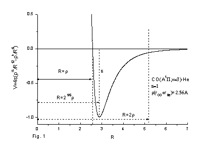
Fig. 1 The qualitative potential energy surface of
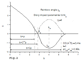
Fig. 2 The qualitative scattering angle with the impact parameter b for
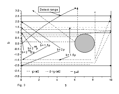
Fig. 3 The analysis of the scattering sources to the differential interference angle
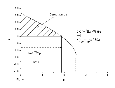
Fig. 4 The detect range of the scattering angle in experiment of the molecular beam
3. 2. 2 The tendency of the differential
interference angle with the scattering angle
To simplify the discussion, we consider that the interaction potential is the rigid sphere
potential, and the scattering angle for the rigid sphere potential is ![]() for
for ![]() , and we only consider the scattering angle from the
"straight line" trajectory when for
, and we only consider the scattering angle from the
"straight line" trajectory when for ![]() , without considering the other two cases. Then one can obtain the
relationship of the differential interference with the impact parameter and the relative
velocity, where the relative velocity can be controlled by choosing the collision angle
, without considering the other two cases. Then one can obtain the
relationship of the differential interference with the impact parameter and the relative
velocity, where the relative velocity can be controlled by choosing the collision angle ![]() of the two sources of the crossed molecular beam,
of the two sources of the crossed molecular beam, ![]() . For
. For ![]() , the transition probability can be estimated by interpolation between
, the transition probability can be estimated by interpolation between ![]() and
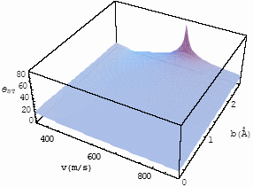
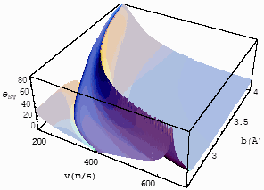
and ![]() of Eq. (34). Figs 5 and 6 are the relationships of the differential
interference angle with the relative velocity impact parameter for
of Eq. (34). Figs 5 and 6 are the relationships of the differential
interference angle with the relative velocity impact parameter for ![]() and for
and for ![]() , where only the source of the “straight line” trajectory is
considered for
, where only the source of the “straight line” trajectory is
considered for ![]() . From
Figs 5 and 6, one finds the long-range interaction potential plays an important role for
the static cell, because the experimental result in the static cell is 610,
which is the average effect to velocity and impact parameter, so some data should be
larger than 610 and some data should be less than 610 in the
differential interference angle, while in case of the short-interaction range of
Fig. 5, all the differential interference angle are less than it. So, in the experiment of
the static cell, the experimental result mainly reflects the influence of the long-range
interaction potential. With the increase of the reduced masses, the repulsive potential
begins contributing to the interference angle inchmeal [10]. To observe the
influence of the short range interaction potential, the experiment in the molecular beam
should be done. According to the discussion in Section 3. 2. 1, the observable
differential interference angle should be measured at the range of
. From
Figs 5 and 6, one finds the long-range interaction potential plays an important role for
the static cell, because the experimental result in the static cell is 610,
which is the average effect to velocity and impact parameter, so some data should be
larger than 610 and some data should be less than 610 in the
differential interference angle, while in case of the short-interaction range of
Fig. 5, all the differential interference angle are less than it. So, in the experiment of
the static cell, the experimental result mainly reflects the influence of the long-range
interaction potential. With the increase of the reduced masses, the repulsive potential
begins contributing to the interference angle inchmeal [10]. To observe the
influence of the short range interaction potential, the experiment in the molecular beam
should be done. According to the discussion in Section 3. 2. 1, the observable
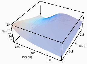
differential interference angle should be measured at the range of ![]() , Figs. 7 and 8 are the relationship of the
differential interference angle with the relative velocity and impact parameter for the
system of CO-He, for
, Figs. 7 and 8 are the relationship of the
differential interference angle with the relative velocity and impact parameter for the
system of CO-He, for ![]() , at T=253 K and 470K.
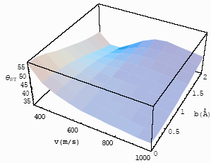
If one compares Figs. 7 and 8, one will find that with the increase of the experimental
temperatures, the differential interference angles increase, i. e., the interference
decrease. Figs. 9 and 10 are the relationship of the differential interference angle with
the relative velocity and impact parameter for
, at T=253 K and 470K.
If one compares Figs. 7 and 8, one will find that with the increase of the experimental
temperatures, the differential interference angles increase, i. e., the interference
decrease. Figs. 9 and 10 are the relationship of the differential interference angle with
the relative velocity and impact parameter for ![]() , for the system of CO-Ne and Ar at 470K. Comparing Figs. 8-10, one can
find that with the increase of the reduced mass, the differential interference angle
increase, i. e., the interference decrease. The changing tendencies of the differential
interference angle with the relative velocity and impact parameter in the molecular beam
experiment are consistent with the experimental results in the static cell. With the
increases of the experimental temperatures and the reduced mass, CQI is of the tendency
that being washed out [3,4,26]. The lower temperature and smaller reduced mass,
the more clearly the CQI can be observed.
, for the system of CO-Ne and Ar at 470K. Comparing Figs. 8-10, one can
find that with the increase of the reduced mass, the differential interference angle
increase, i. e., the interference decrease. The changing tendencies of the differential
interference angle with the relative velocity and impact parameter in the molecular beam
experiment are consistent with the experimental results in the static cell. With the
increases of the experimental temperatures and the reduced mass, CQI is of the tendency
that being washed out [3,4,26]. The lower temperature and smaller reduced mass,
the more clearly the CQI can be observed.
 |
 |
| Fig.5 The
differential interference angle with velocity and impact parameter for CO-He at T=253K for |
Fig.6 The
differential interference angle with velocity and impact parameter for CO-He at T=253K for |
 |
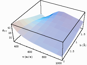 |
| Fig.7 The
differential interference angle with velocity and impact parameter for CO-He at T=253K for |
Fig.8 The
differential interference angle with velocity and impact parameter for CO-He at T=470K for |
 |
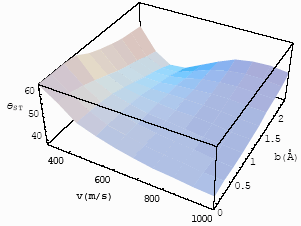 |
| Fig.9 The
differential interference angle with velocity and impact parameter for CO-Ne at T=470K for |
Fig.10 The
differential interference angle with velocity and impact parameter for CO-Ar at T=470K for |
4 CONCLUSION
The collision-induced quantum interference on rotational energy transfer is studied, and the differential, the integral interference angle
and the relationship between them are obtained. The relationship between the differential
interference angle and the scattering angle in the experiment of the molecular beam at the
observed range is discussed.
REFERENCES
[1] Sun M T, Liu J, Sun W Z, et al. Chem. Phys. Lett, 2002, 365: 244.
[2] Lorenz K T , Chandler D W, Barr J W, et al. Science, 2001, 293: 2063.
[3] Sha G H, He J B, Jiang B, et al. J. Chem. Phys, 1995, 102: 2772.
[4] Chen X L, Sha G H, Jiang B, et al. J. Chem. Phys, 1996, 105: 8661.
[5] Chen X L, Chen H M., Li J, et al. Chem. Phys. Lett, 2000, 318: 107.
[6] Liu J, Sun M T, Jiang B, et al. Chem. Phys. Lett, 2004, 388: 306.
[7] Sun M T, Ma F C, Sha G H. Chem. Phys. Lett, 2003, 374: 20.
[8] Sun M T, Sha G H, Cong S L, et al. Chem. Phys. Lett, 2001, 339: 413.
[9] Sun M T, Liu J, Ma F C, et al. Chem Phys, 2001, 274: 175.
[10] Tian H M, Sun M T, Sha G H. Phys. Chem. Chem. Phys, 2002, 4: 5123.
[11] Sun M T, Wang W L, Song P, et al. Chem. Phys. Lett, 2004, 386: 430.
[12] Sun M T, Tian H M, Sha G H. Chin. J. Chem. Phys, 2002, 15: 175.
[13] Sun M T, Tian H M, Sha G H. Chem. Phys. Lett, 2002, 361: 8.
[14] Li Y Q, Sun M T, Ma F C. Chin. J. Chem. Phys, 2004, 17: 395.
[15] Tian H M, Sha G H, Zhang C H. Chin. J. Chem. Phys, 2004, 17: 283.
[16] Sha G H, Zhang C H. Acta Physics-Chemical Sinica, 2004, 20: 1010.
[17] Chandler D W, Houston P L. J. Chem. Phys, 1987, 87: 1445.
[18] Eppink A T J B, Parker D H. Rev. Sci. Instrum, 1997, 68: 3477.
[19] Kohguchi H, Suzuki T, Alexander M H. Science, 2001, 294: 5543.
[20] Lin J J, Zhou J, Shiu W,etal. Rev. Sci. Instrum, 2003, 74: 2495.
[21] Sun M T, Lee Y Q, Ma F C, et al. Chem. Phys. Lett, 2003, 371: 342.
[22] Sun M T, Sha G H. Chem. Phys. Lett, 2003, 378: 148.
[23] Levine R D, Bernstein R B. Molecular Reaction Dynamics and Chemical Reactivity,
Oxford University Press, Oxford, 1987.
[24] Gray C G, Kranendonk J Van. Can. J. Phys, 1966, 44: 2411.
[25] Sharma R D, Brau C A. J. Chem. Phys, 1969, 50: 924.
[26] Park S M and Diebold D J. Phys. Rev. A, 1990,42: 417.
[27] Alexander M H. J. Chem. Phys, 1982, 76: 5974.
[28] Freed K F, Tric C. Chem. Phys, 1978, 33: 249.
[29] Li L, Zhu Q S, Lyyra A M, et al. J. Chem. Phys, 1992, 97: 8835.
[30] Herzberg G, Molecular Spectra and Molecular Structure, Vol I: Spectra of Diatomic
Molecule, Van Nostrand, New York, 1950.
[31] Lefebvre-Brion H., Field R W, Perturbations in the Spectra of diatomic Molecules,
Academic Press, New York, 1986.
[32] McCury C W, Miller W H. J. Chem. Phys, 1977, 67: 463.
[33] Tilford S G, Simmons J D. J. Phys. Chem. Ref. Data, 1972, 1: 147.
转动传能中的碰撞量子干涉效应:微分干涉角和散射角之间的关系
孙萌涛#,宋朋,李春霞,王伟丽,李永庆,马凤才*
(辽宁大学物理系,沈阳,110036)
摘要 在分子内部转动传能的静态池实验中观察到碰撞量子干涉效应,并且测得积分干涉角。为了获得更加精确的信息,要采用分子束实验,通过此实验可获得微分干涉角和散射角之间的关系。本文考虑各项异性L-J相互作用势,应用含时微扰理论的一级波恩近似,在分子束实验的条件下,建立在原子-双原子分子体系中碰撞量子干涉的理论模型。采用正确的观测途径,讨论了微分干涉角随散射角(包括碰撞参数、速率以及碰撞伴)的变化趋势。
关键词:量子干涉效应,微分干涉角,散射角。